Refillable container with a zero waste dispensing system

Inactive Publication Date: 2014-01-23
PACK FLOW CONCEPTS
View PDF17 Cites 11 Cited by
  • Summary
  • Abstract
  • Description
  • Claims
  • Application Information

AI Technical Summary

Benefits of technology

The invention is a collapsible container with a base fixture that connects to a semi-rigid outer shell, allowing the insert to fold or collapse during use. The base fixture prevents this and ensures that no substance is wasted during the pouring process. This invention minimizes manufacturing and transportation costs and reduces environmental burdens associated with traditional containers. It is a zero waste dispensing system that can be used refillably.

Problems solved by technology

Very substantial transportation and handling costs are involved with processing such semi-rigid bottles from a manufacturing plant to a filling plant.
It is apparent that the costs of transporting large, light empty containers combined with the costs of separating the empty containers for processing during filling is a very substantial component of the overall costs of manufacture and delivery of such liquids and flowable substances to an end user.
This gives rise to grave environmental concerns.
Because the bottles 10 must have adequate structural integrity to withstand the described processing, including retail display, the bottles 10 invariably pose environmental challenges.
While expensive and time-consuming efforts are being undertaken to recycle and reuse the materials of these semi-rigid plastic bottles, it is apparent that recycling will never be completely successful, and used semi-rigid plastic containers continue to pollute our environment in ever greater quantities.

Method used


Image

  • Refillable container with a zero waste dispensing system
  • Refillable container with a zero waste dispensing system
  • Refillable container with a zero waste dispensing system

Examples


embodiment 100

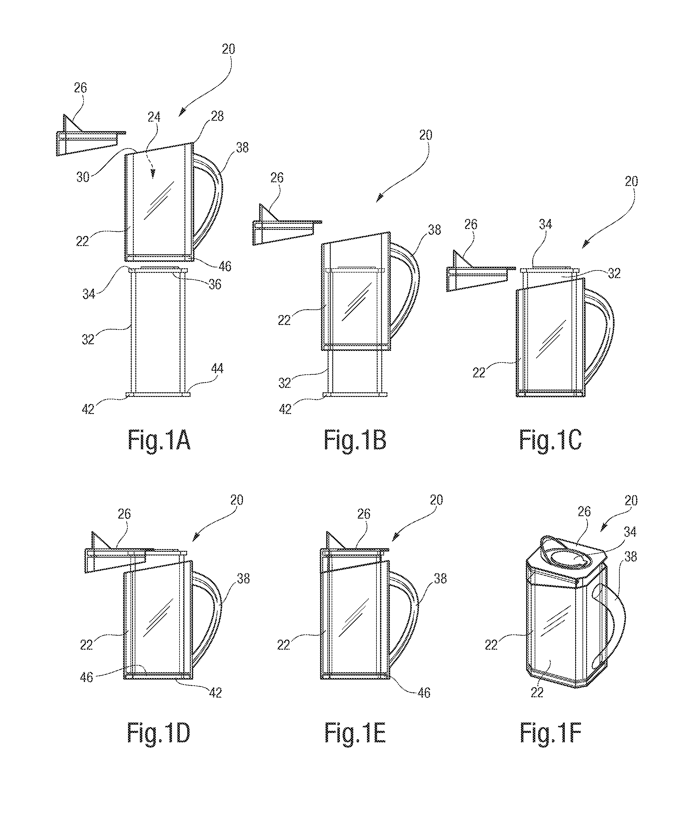
[0086]As described above, instead of relying upon the force of gravity to pour the contents out of the collapsible insert 110 upon tipping of the FIG. 1A container 20, the thick-liquid embodiment 100 utilizes varying efficient but complex extractions mechanisms to move the thick liquid within the insert 110 through the discharge cap 106 and out of the container 100.

[0087]A first extraction mechanism is shown generally in FIGS. 15-31. For convenience, this first extraction mechanism will be referred to herein as a helical track extraction mechanism. (As described above, for purposes herein, the phrase “helical track” is intended to include both a groove defined to descend below an inside surface 122 of the shell as well as a ridge defined to extend above the inside surface 122 of the shell. It is expected that most helical track extraction mechanism embodiments will be in the form a groove.)

[0088]As shown in FIG. 15 a preferred embodiment includes a first helical track 124 and a seco...

embodiment 240

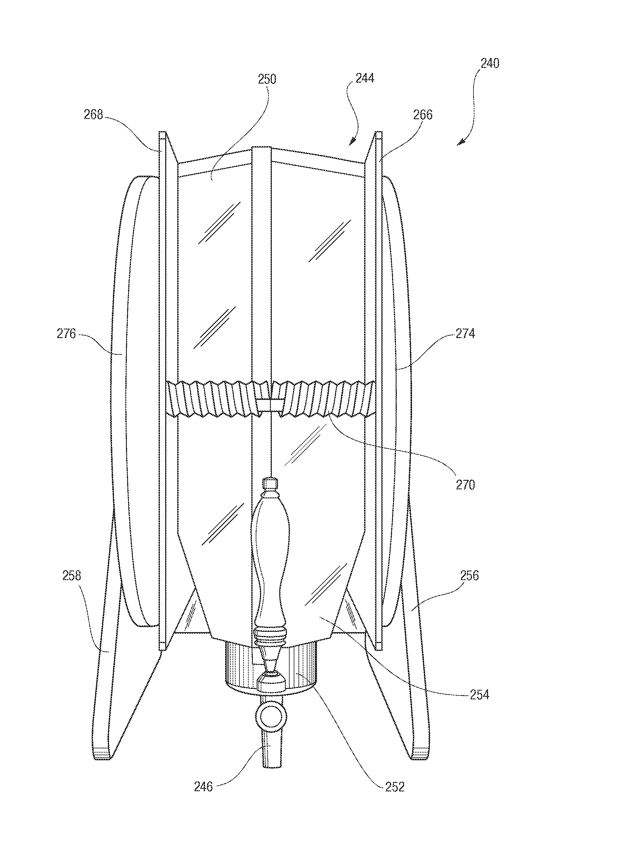
[0102]FIG. 34 shows that helical axle refillable container 242 may be pivotally mounted between a first pivot base 256 and a second pivot base 258. The semi-rigid outer shell 242 is pivotally secured between the pivot bases 256, 258 so the shell 242 may be deployed in a dispensing mode as shown in FIG. 34 or in a refill mode as shown in FIG. 35. The outer shell 242 also includes a front wall 260, top wall 262, a bottom wall 264, a first side wall 266 and a second side wall 268 (shown only in FIG. 36). In this helical axle embodiment 240, the side wails 266, 268 may be rigidly secured to the front, top and bottom walls 260, 262, 264 so that opposed compression plates may be secured within the shell 242.

[0103]Alternatively, and as shown in FIGS. 34-36, and FIGS. 38, 39, the side walls 260, 262 may be slidably secured to the front, top and bottom walls 260, 262, 264 to thereby serve as compression plates 266, 268 to apply pressure to the collapsible insert 250. As shown best in FIGS. 3...


PUM

PropertyMeasurementUnit
Flow rateaaaaaaaaaa

Abstract

The refillable container (20) includes a semi-rigid outer shell (22) that defines an interior void (24) and includes a detachable pour spout (26). The container (20) may be refilled with a plurality of collapsible inserts (32). Instead of rigid beverage bottles and other flowable substance containers, the collapsible inserts (32) may be transported from a manufacturing to a filling facility in a collapsed state (76), and do not have to include semi-rigid materials thereby minimizing disposal requirements. A tilt-pouring embodiment (20), a helical track embodiment (100), a helical axle embodiment (240) and an air-bladder embodiment (300) of refillable containers having common components permit dispensing of products from the containers (20, 100, 240, 300) to achieve virtually zero waste of the products.

Description

CROSS-REFERENCE TO RELATED APPLICATIONS[0001]This Application claims the benefit of U.S. Provisional Patent Application Ser. No. 61 / 462,971 that was filed on Feb. 10, 2011 entitled “Flow Bottle Design and Manufacture” and U.S. Provisional Patent Application Ser. No. 61 / 516,804 that was filed on Apr. 8, 2011 entitled “Flow Bottle Twist Dispenser Design and Manufacturing”.TECHNICAL FIELD[0002]This disclosure relates to structures for containing and pouring liquids and flowable substances (such as fruit juice, soda, laundry detergent, kitty litter, pelletized animal food, etc.), and in particular relates to a refillable, reusable container that receives and secures a collapsible insert that contain the liquids or flowable substances.BACKGROUND ART[0003]It is well known that traditional containers for dispensing liquids and flowable substances are generally blow-molded bottles made of varying types of thermoplastics. Every supermarket has literally hundreds of different types of such se...

Claims


Application Information

Patent Timeline
IPC IPC(8): B65D35/30
CPCB65D21/08B65D25/48B65D71/70B65D77/06B65D35/30Y10T29/49826
Inventor DERBY, STEPHENMCFADDEN, JOHNBROWN, DAVIDECKERT, EUGENE
Owner PACK FLOW CONCEPTS
Why Eureka
Try Eureka