Food Processor

a technology for food processors and threshers, which is applied in the field of motorised kitchen appliances, can solve the problems of introducing unwanted vibration and extra stress on components, and achieve the effect of reducing the transfer of vibration

Active Publication Date: 2014-01-23
BREVILLE HLDG PTY LTD
View PDF13 Cites 20 Cited by
  • Summary
  • Abstract
  • Description
  • Claims
  • Application Information

AI Technical Summary

Benefits of technology

[0066]Preferably, an exterior housing of the bushing assembly cooperates with the feed tube. More preferably, an elastomeric boot is between the bush assembly and the lid for reducing transfer of vibration from the spindle to the lid.

Problems solved by technology

These features tend to introduce unwanted vibration and extra stresses on the components.

Method used


Image

  • Food Processor
  • Food Processor
  • Food Processor

Examples


Embodiment Construction

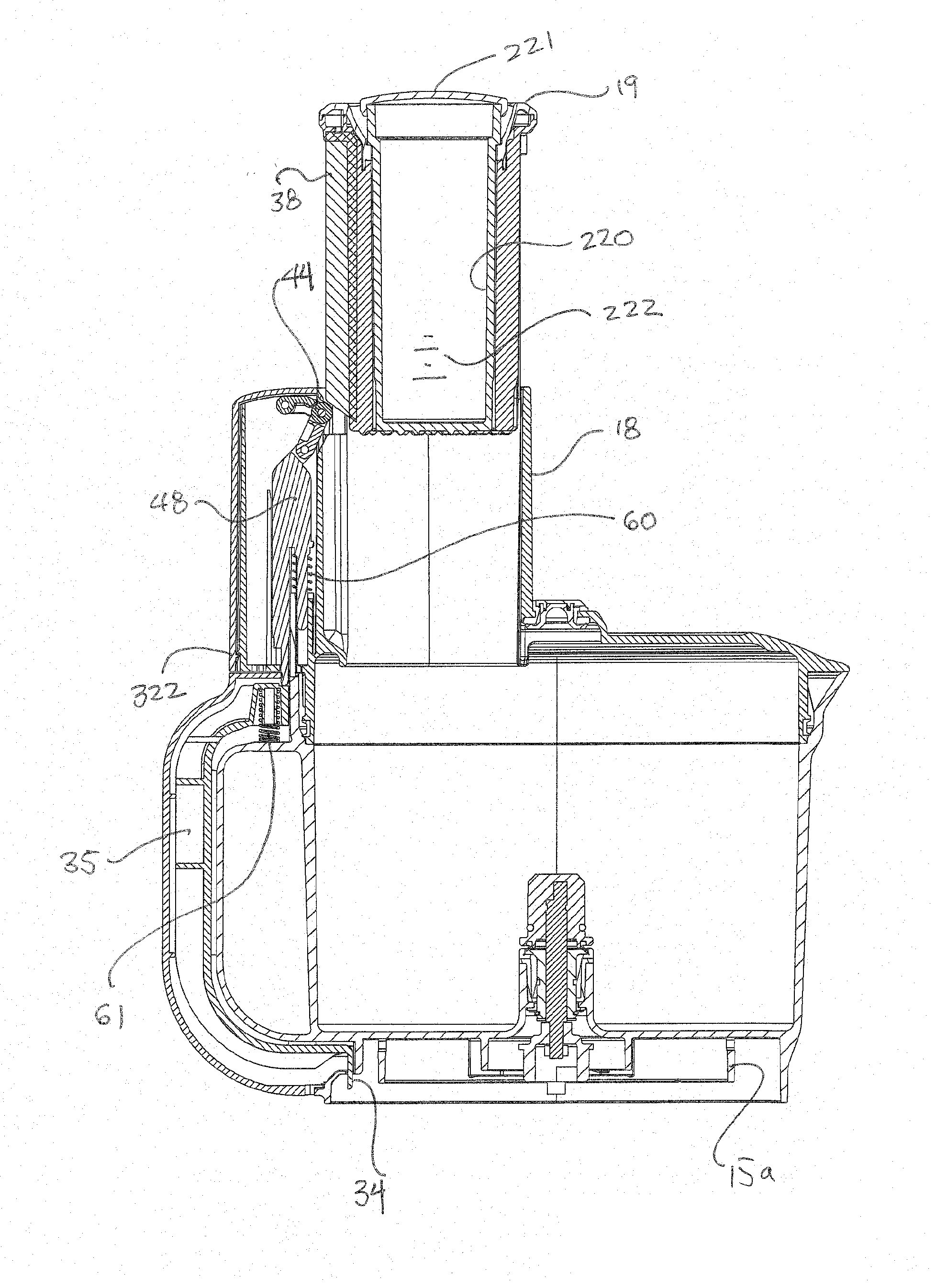
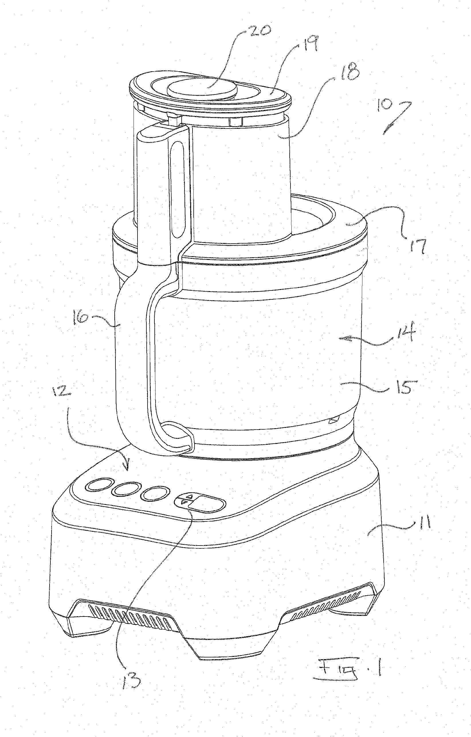
[0144]As shown in FIG. 1, a food processor 10 comprises a base with internal motor 11, user operated controls 12, an electronic display 13 and a processing container 14. The container 14 further comprises a bowl 15 with a handle 16 and a lid 17 with an integral and wide feed tube 18. The feed tube 18 receives a pusher 19. In this example, the pusher accommodates a smaller second pusher 20.

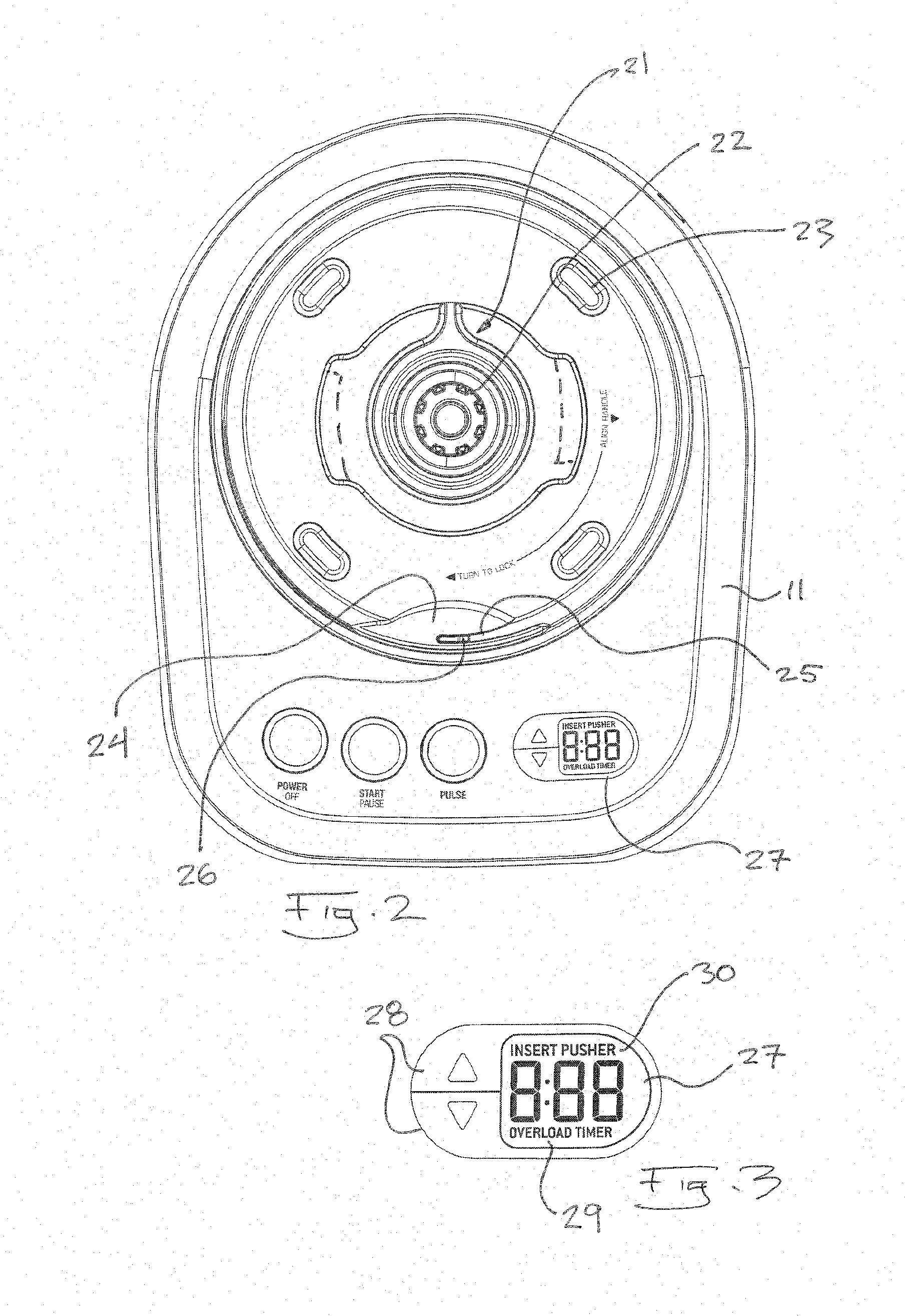
[0145]As shown in FIG. 2, the base 11 is formed from die cast metal. The uppermost surface features a polymeric, female bayonet fitting 21 for receiving and restraining the container 14. A female coupling component 22 is located within and protrudes through the bayonet fitting 21. The polymeric container 14 is supported above the upper surface of the die cast base by (in this example) four acetal wear pads 23 that prevent the bowl from contacting and thus scratching the coating on the die cast base. Thus, owing to the polymeric bayonet fitting 21 and the acetal pads 23, the bowl's contact with the ...


PUM


Abstract

A food processor is provided with a wide feed tube. The food processor has a pusher that cooperates with a safety mechanism. The safety mechanism comprises a linkage assembly that prevents the food processor's motor from operating unless the pusher is inserted into the feed tube.

Description

FIELD OF THE INVENTION[0001]The invention relates to motorised kitchen appliances and more particularly to a food processor.[0002]The invention has been developed primarily for use as a food processor and will be described hereinafter with reference to this application. However, it will be appreciated that the invention is not limited to this particular field of use.BACKGROUND OF THE INVENTION[0003]Any discussion of the prior art throughout the specification should in no way be considered as an admission that such prior art is widely known or forms part of the common general knowledge in the field.[0004]Food processors are well known. Trends in domestic food processors indicate a desire, by consumers, for a food processor with a wider feed tube. A wider feed tube means that more ingredients and larger ingredients can be introduced into the device, thereby shortening food preparation time and adding convenience. However, food processors with sufficiently large feed tubes are expected...

Claims


Application Information

Patent Timeline
Patent Type & Authority Applications(United States)
IPC IPC(8): A47J43/07
CPCA47J43/0794A47J43/0772A47J43/0788A47J43/046
Inventor ARMSTRONG, DANIELWIDANAGAMAGE DON, LOCHANA SUBASEKARAHENSEL, KEITH JAMES
Owner BREVILLE HLDG PTY LTD
Why Eureka
Try Eureka