Radar field of view expansion with phased array transceiver

a phased array transceiver and radar technology, applied in the field of radar equipment, can solve problems such as false detection, and achieve the effect of increasing the available field of view

Inactive Publication Date: 2014-01-23
TOYOTA MOTOR ENGINEERING & MANUFACTURING NORTH AMERICA
View PDF15 Cites 32 Cited by
  • Summary
  • Abstract
  • Description
  • Claims
  • Application Information

AI Technical Summary

Benefits of technology

[0011]A radar controller includes an electronic circuit, and may be used to steer transmit beams and receive beam(s). Transmit and receive beams may be steered together, using phased array approaches, to align grating lobes of the transmit and receive beams. For example, the main lobe of the transmit and receive beam may be angularly aligned as the beams are steered across the field of view of the antenna. Steering of both transmit and receive beams increases the available field of view.

Problems solved by technology

Such objects often give false detections (i.e. false detection of collision hazards) which may trigger an emergency stop in a conventional ACC system.

Method used


Image

  • Radar field of view expansion with phased array transceiver
  • Radar field of view expansion with phased array transceiver
  • Radar field of view expansion with phased array transceiver

Examples


Embodiment Construction

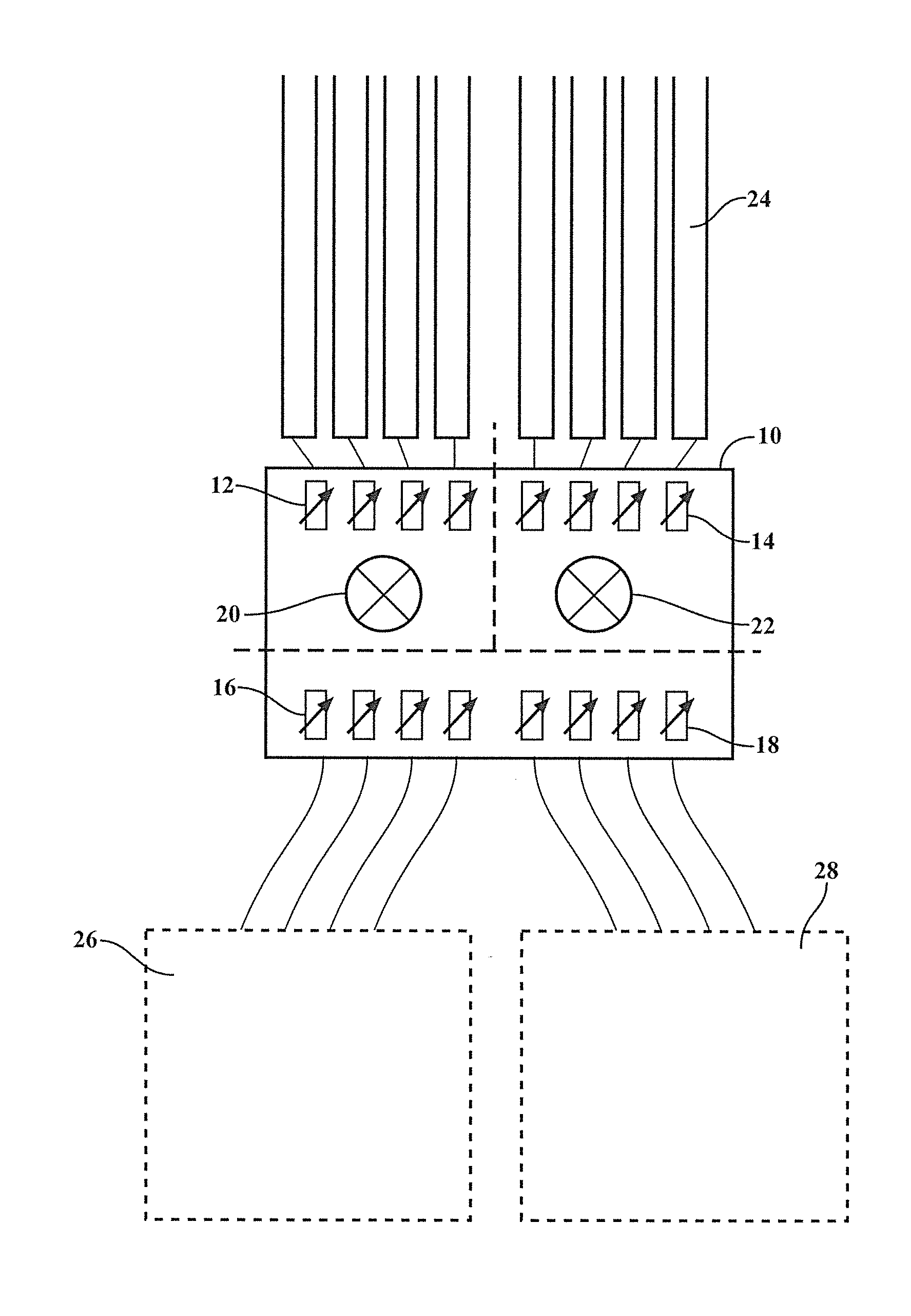
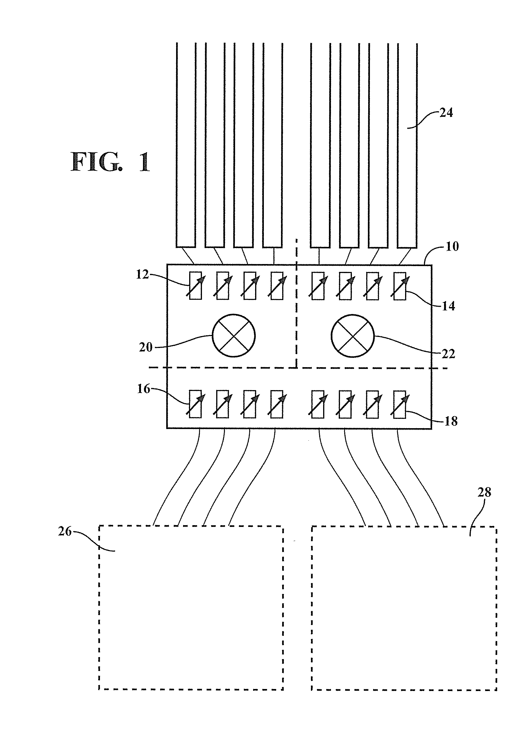
[0016]Examples of the invention include a radar apparatus including two receive antenna arrays, each receive antenna array having a dedicated RF mixer and set of phase shifters. Each antenna element may have an associated phase shifter, for example a voltage controlled phase shifter. The apparatus may also include one or more transmit antenna phased arrays, each with a set of dedicated phase shifters. Example apparatus are configured so that all phase shifters and RF mixers are included in a single RF integrated circuit. The transmit antenna arrays are mounted at different elevations, with at least one array directed towards the road surface and receiving signals from metal objects generally in the plane of the road surface. One or more additional transmit arrays are directed towards potential targets that are located on the road surface, such as other vehicles, pedestrians, animals, and the like. In this context, the target is an object providing a radar signal, which may pose a th...


PUM


Abstract

Examples of the invention include radar apparatus having at least two phased array transmitters, each having a different elevation corresponding to heights of detected targets relative to the road surface. A low elevation transmit beam is directed at the road surface, and used to identify metal objects in the road surface, which often cause false detections in conventional devices but may not be actual collision hazards. A higher elevation transmitted beam is used to detect actual collision hazards to the vehicle.

Description

FIELD OF THE INVENTION[0001]The invention relates to radar apparatus, such as phased array radar.BACKGROUND OF THE INVENTION[0002]Radar apparatus are useful for various applications, for example collision avoidance in improved vehicular cruise controls. It would be very useful to develop improved radar, for example radar apparatus that is less susceptible to false detections.SUMMARY OF THE INVENTION[0003]Examples of the present invention include an improved automotive radar apparatus. The apparatus includes a receive antenna array, one or more transmit antenna arrays, and electronic circuitry for analyzing the radar signal. In some examples, a single RF (radio frequency) chip includes receiver phase shifters, transmitter phase shifters, and RF mixers for both the transmit and receive arrays. The presence of two RF mixers on the chip allows two independent beams to be steered simultaneously, e.g. for both receive and transmit beam control. The transmit and receive beams may be steere...

Claims


Application Information

Patent Timeline
Patent Type & Authority Applications(United States)
IPC IPC(8): G01S13/93G01S13/931
CPCG01S7/2813G01S13/931G01S2013/0254H01Q1/3233G01S2013/9321G01S2013/9322
Inventor LEE, JAE SEUNGSCHMALENBERG, PAUL DONALD
Owner TOYOTA MOTOR ENGINEERING & MANUFACTURING NORTH AMERICA
Why Eureka
Try Eureka