
Radar apparatus and method

Active Publication Date: 2014-01-23
SONY CORP
View PDF5 Cites 33 Cited by
  • Summary
  • Abstract
  • Description
  • Claims
  • Application Information

AI Technical Summary

Benefits of technology

The present patent is about a radar system and method that can improve radar's ability to resolve ranges without needing more bandwidth. This system can also create a 3D image of a scene and show different layers in depth. Additionally, the system can display 2D layer images of a 3D scene by grouping together receive signal samples from the same depth bin and target. This allows for more accurate imaging and recognition of targets at different depths.

Problems solved by technology

Although the FFT is computationally efficient, it provides a range resolution that, in practice, hardly achieves the theoretical range resolution.

Method used


Image

  • Radar apparatus and method
  • Radar apparatus and method
  • Radar apparatus and method

Examples


Embodiment Construction

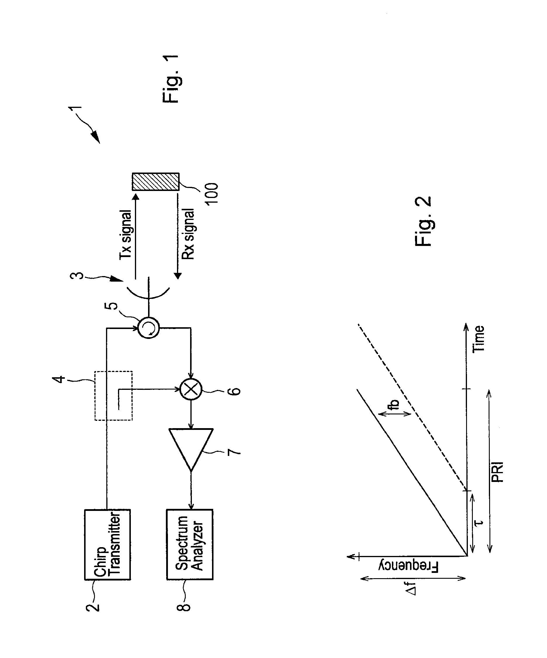
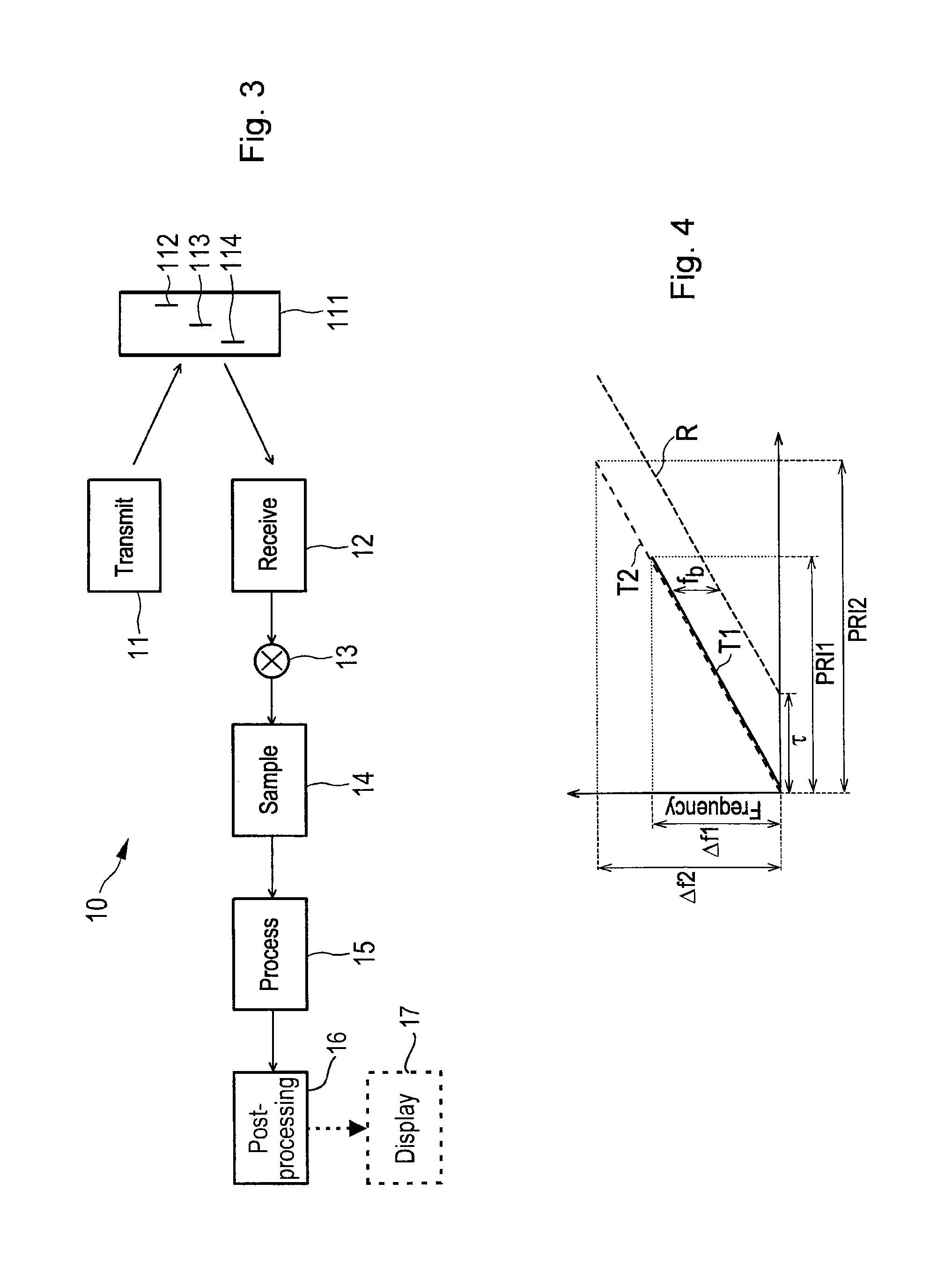
[0034]Referring now to the drawings, wherein like reference numerals designate identical or corresponding parts throughout the several views, FIG. 1 shows an embodiment of a conventional FMCW radar apparatus 1. A thorough explanation of FMCW is given in G. Brooker, “Understanding Millimeter Wave FMCW Radars”, 1st International Conference on Sensing Technology, Nov. 21-23, 2005, Palmerston North, New Zealand, p. 152-157. Such a FMCW radar 1 transmits a continuous wave signal that is frequency modulated (frequency is changing with time) to produce a chirp pulse by a chirp transmitter 2. This is transmitted to the object 100 (e.g. included in a scene) to be examined by a co-located (monostatic) antenna 3 and is also fed to the receiver via a coupler 4. Depending upon the properties of the object 100 the transmitted signal will be reflected by the object 100 and be received by the receiver of the FMCW radar, i.e. the co-located antenna 3. A duplexer or circulator 5 serves for time multi...


PUM


Abstract

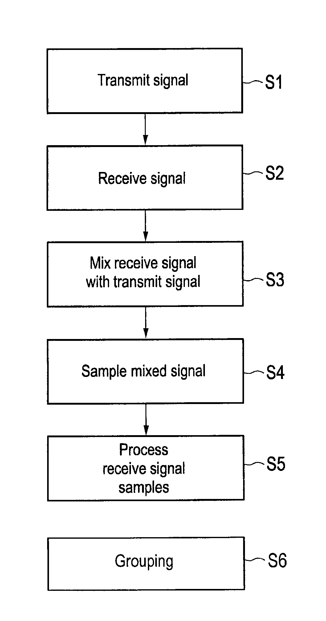
A radar apparatus for obtaining a higher range resolution than conventional radar apparatus without increasing the bandwidth comprises a transmitter antenna that transmits a frequency modulated transmit signal having a transmit bandwidth and a receiver antenna that receives a receive signal reflected from said scene in response to the transmission of said transmit signal. A mixer mixes said receive signal with said transmit signal to obtain a mixed receive signal, a sampling unit samples said mixed receive signal to obtain receive signal samples from a period of said receive signal, and a processor processes said receive signal samples by defining a measurement matrix and determines the positions of one or more targets of the scene by applying compressive sensing using said measurement matrix and said receive signal samples. A post-processor groups together receive signal samples having a depth within the same depth bin and belonging to the same target.

Description

BACKGROUND[0001]1. Field of the Disclosure[0002]The present disclosure relates to a radar apparatus and a corresponding radar method. Further, the present disclosure relates to a processing apparatus and method for use in such a radar apparatus and method, respectively. Still further, the present disclosure relates to a computer program for implementing said processing method and to a computer readable non-transitory medium storing such a computer program.[0003]2. Description of the Related Art[0004]The depth (range) resolution of frequency modulated continuous wave (FMCW) radar systems improves (gets finer) by increasing the bandwidth of the transmitted chirp. Conventionally, the information about the range of the targets is extracted with a Fast Fourier Transform (FFT) of the received sampled data. Although the FFT is computationally efficient, it provides a range resolution that, in practice, hardly achieves the theoretical range resolution.[0005]Some signal processing techniques...

Claims


Application Information

Patent Timeline
IPC IPC(8): G01S7/41
CPCG01S7/412G01S7/41G01S7/418G01S13/34
Inventor NOGUEIRA-NINE, JUAN
Owner SONY CORP
Learn More