Conformal Electro-Textile Antenna and Electronic Band Gap Ground Plane for Suppression of Back Radiation From GPS Antennas Mounted on Aircraft

a technology of electrotextile antennas and ground planes, applied in the direction of antenna earthings, antenna details, antennas, etc., can solve the problems of weak gps signals, gps antennas on aircraft can be either jammed or interfered with by a large number of sources, and achieve the effect of suppressing back radiation

Active Publication Date: 2014-01-23
MITRE SPORTS INT LTD
View PDF4 Cites 16 Cited by
  • Summary
  • Abstract
  • Description
  • Claims
  • Application Information

AI Technical Summary

Benefits of technology

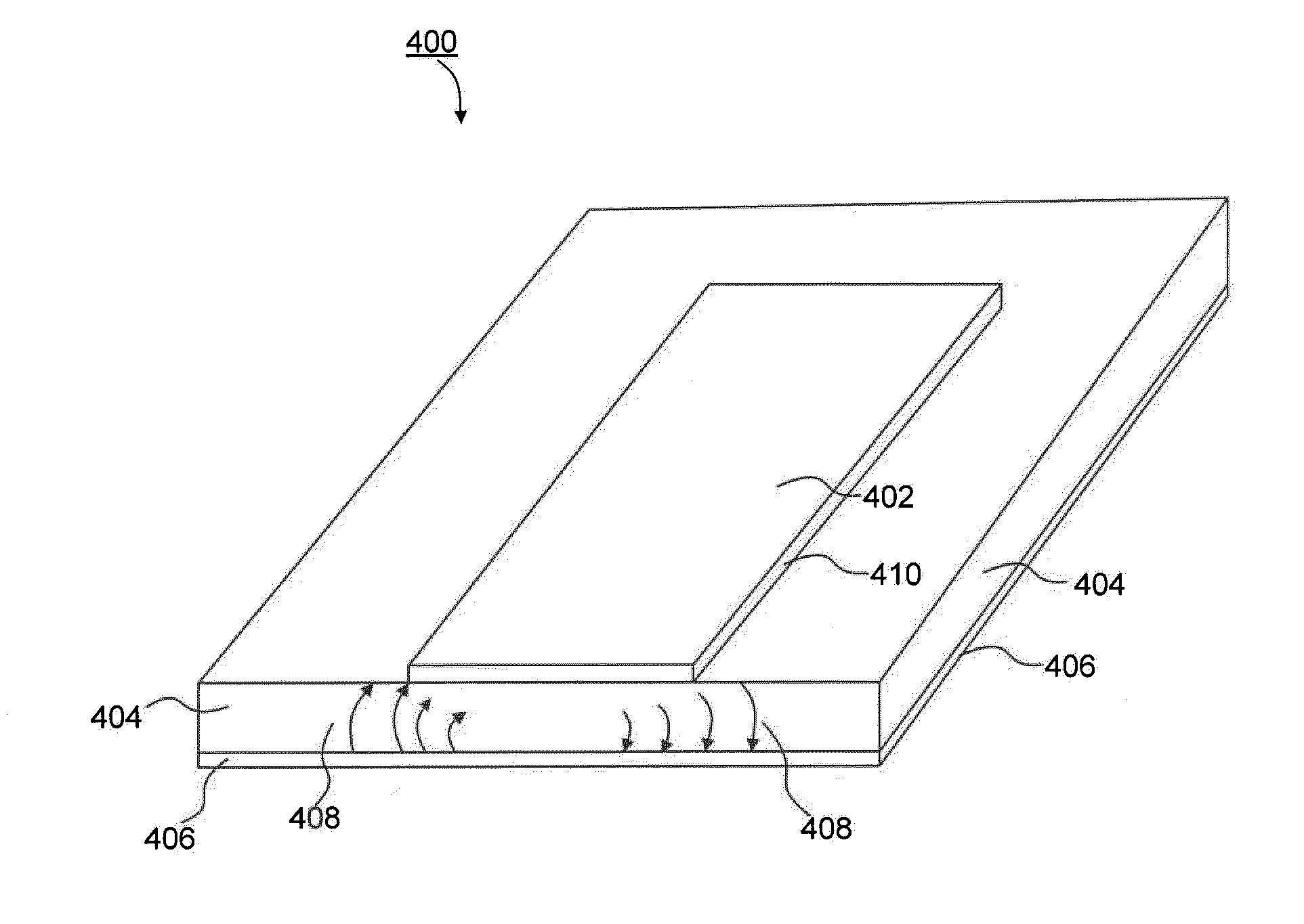
[0012]The RSW antenna and EBG ground plane work in conjunction to suppress back radiation caused by curved surface diffraction. The RSW antenna and the EBG ground plane are designed to work primarily in the two principal frequency bands—either the L1 and L2 bands of the modernized GPS system or the L1 and L5 bands. The

Problems solved by technology

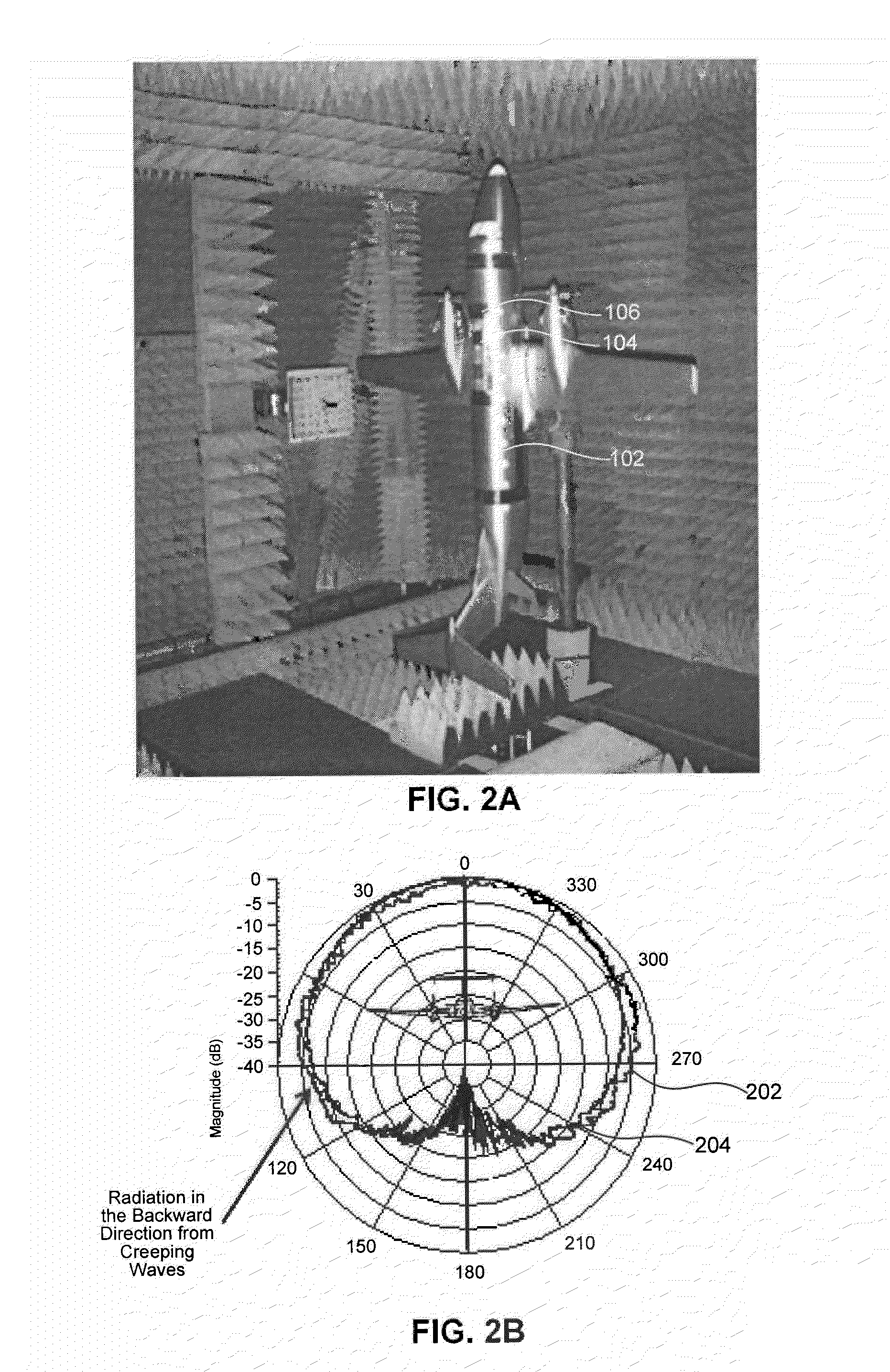
It is this radiation that creates the back-lobes in the radiation pattern of the antenna that make these GPS antennas very vulnerable to interference from strong radiating sources located on the ground.
GPS antennas on aircraft can be either jammed or interfered with by a large number of sources.
GPS signals are very weak due to their long travel distances from GPS satellites that are located 20,000 kilometers above the earth.
Hence they encounter a large amount of “space loss” during their long travel distances.
Microstrip “patch” antennas are commonly used for building GPS antennas mounted on aircraft due to their low profile for reducing aerodynamic drag and their low cost and ease of manufacture

Method used


Image

  • Conformal Electro-Textile Antenna and Electronic Band Gap Ground Plane for Suppression of Back Radiation From GPS Antennas Mounted on Aircraft
  • Conformal Electro-Textile Antenna and Electronic Band Gap Ground Plane for Suppression of Back Radiation From GPS Antennas Mounted on Aircraft
  • Conformal Electro-Textile Antenna and Electronic Band Gap Ground Plane for Suppression of Back Radiation From GPS Antennas Mounted on Aircraft

Examples


Embodiment Construction

[0049]This specification discloses one or more embodiments that incorporate the features of this invention. The disclosed embodiment(s) merely exemplify the invention. The scope of the invention is not limited to the disclosed embodiment(s). The invention is defined by the claims appended hereto.

[0050]The embodiment(s) described, and references in the specification to “one embodiment,”“an embodiment,”“an example embodiment,” etc., indicate that the embodiment(s) described may include a particular feature, structure, or characteristic, but every embodiment may not necessarily include the particular feature, structure, or characteristic. Moreover, such phrases are not necessarily referring to the same embodiment. Further, when a particular feature, structure, or characteristic is described in connection with an embodiment, it is understood that it is within the knowledge of one skilled in the art to effect such feature, structure, or characteristic in connection with other embodiments...


PUM


Abstract

An antenna system having reduced back radiation is disclosed. The antenna system includes an antenna and ground plane. The antenna includes electro-textiles and is configured to operate in at least the frequency range between 1.1-1.6 GHz. The ground plane includes electro-textiles and is configured to operate as a frequency selective surface with electronic band gap characteristics to suppress edge and curved surface diffraction effects. In this system, the antenna and ground plane are configured to be located on a curved surface and to radiate with a directional radiation pattern having attenuated back lobes.

Description

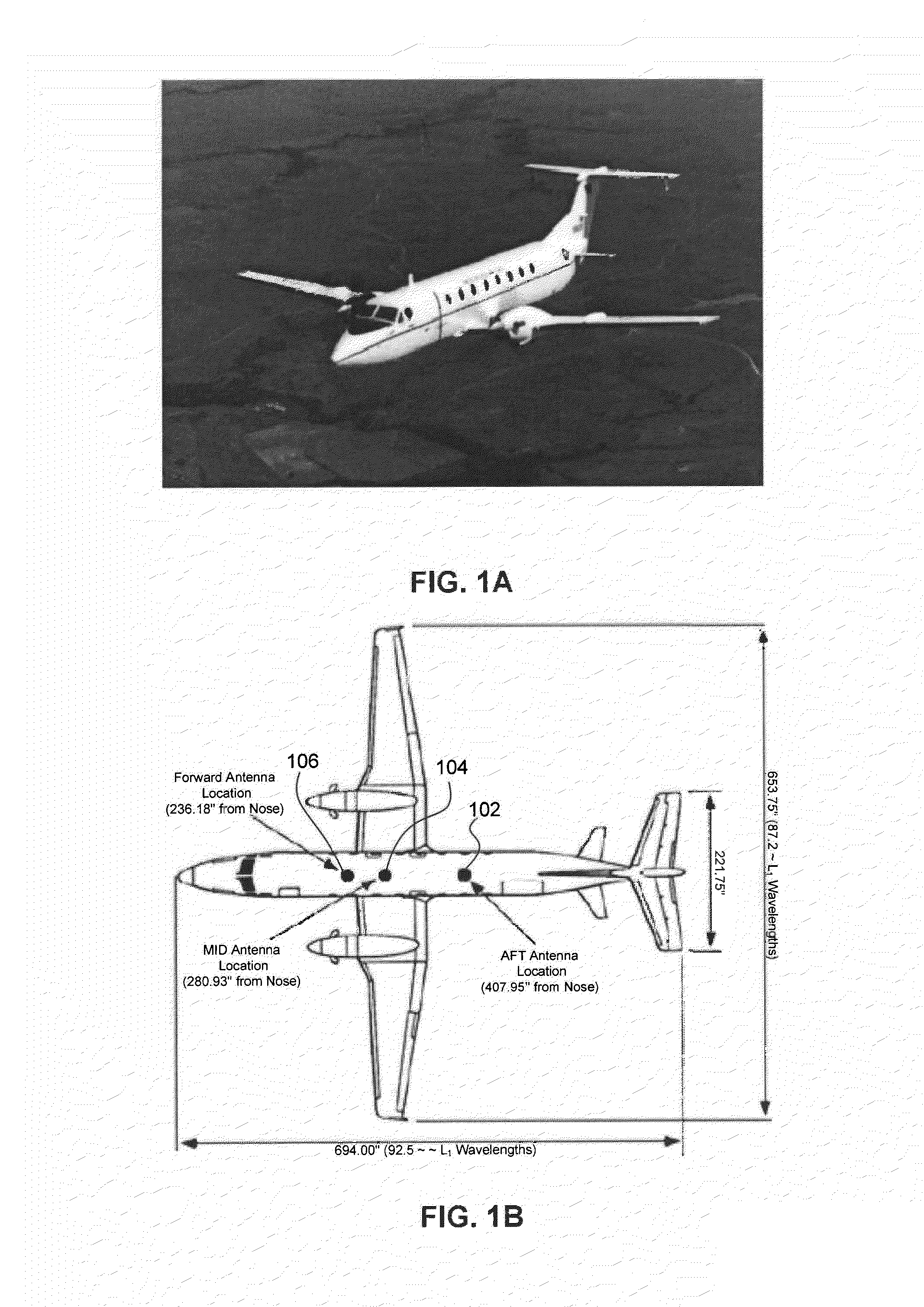
BACKGROUND[0001]1. Field of the Invention[0002]This disclosure relates to antenna based systems and methods for aircraft navigation.[0003]2. Background[0004]Global Positioning System (GPS) antennas used for navigation on aircraft generate considerable backward radiation which is directed downwards towards the ground. This radiation is primarily caused by what is known as “creeping waves” generated by curved surface diffraction. A portion of the RF energy radiated by the GPS antenna is diffracted around the smooth cylindrical surface of the fuselage of the aircraft. This diffracted energy then propagates or “creeps” around the surface fuselage continuously shedding energy as it propagates until it dies out. It is this radiation that creates the back-lobes in the radiation pattern of the antenna that make these GPS antennas very vulnerable to interference from strong radiating sources located on the ground.[0005]GPS antennas on aircraft can be either jammed or interfered with by a lar...

Claims


Application Information

Patent Timeline
IPC IPC(8): H01Q1/48
Inventor RAO, BASRUR RAMAROSARIO, EDDIE NELSON
Owner MITRE SPORTS INT LTD
Why Eureka
Try Eureka