Security wrap with breakable conductors

a technology of conductors and security wraps, applied in the direction of burglar alarm mechanical actuation, identification means, instruments, etc., can solve the problems of little tamper resistance or indication of tampering, physical difficulty in removing security wraps, and inability to encapsulate or coat security wraps with resins

Active Publication Date: 2014-01-30
JOHNSON ELECTRIC SA
View PDF7 Cites 51 Cited by
  • Summary
  • Abstract
  • Description
  • Claims
  • Application Information

AI Technical Summary

Benefits of technology

[0027]In another aspect thereof, the present invention provides a security wrap for preventing unauthorized access to a device having an alarm circuit and components mounted on a printed circuit board (PCB), comprising: a substrate having a first side and a second side opposite to each other; a release layer having a predetermined pattern of release ink disposed over the first side of said substrate; a security screen disposed over said release layer and the first side of said substrate and including a pair of screen terminals coupled to the alarm circuit of the device and a conductive track between the pair of screen terminals; and a layer of adhesive covering the first said substrate and bonding the first side of said substrate to the PCB of the device with said security screen and said release layer sandwiched there between.
[0028]Preferably, further comprising: a dielectric layer disposed between said security screen and said re

Problems solved by technology

Removal of the security wrap is physically difficult due to the manner in which the security wrap is attached to the device, usually by gluing, soldering or encapsulation with a resin material.
However, they offer little in the way of tamper resistance or indication of tampering except by visual inspection.
Some systems have an alarm circuit which may disable the device or simply give a visual indication that the security wrap has been removed, but there is no detection of an attempt to

Method used


Image

  • Security wrap with breakable conductors
  • Security wrap with breakable conductors
  • Security wrap with breakable conductors

Examples


Embodiment Construction

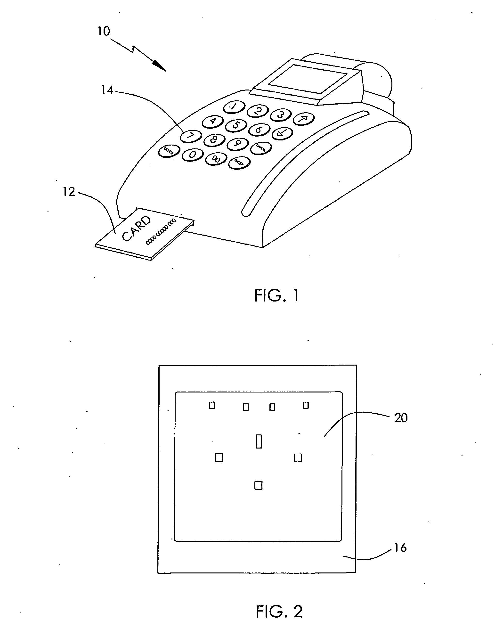
[0055]FIG. 1 illustrates a POS device 10 as an example of where the security wrap is used. The POS has a slot for receiving a card 12, such as a credit card containing confidential information such as account details, etc. The device 10 also has buttons 14 for entering instructions for controlling the device. Inside the PUS 10 is an electronic circuit comprising circuit board with a memory chip and / or a microprocessor which may contain or momentarily access confidential information. The security wrap 20 may be placed over the entire circuit board or over just a portion of the board, as will be described herein after, depending on system requirements.

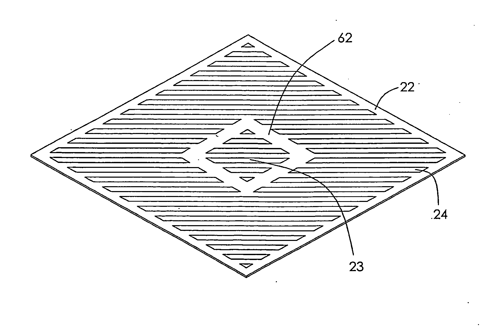
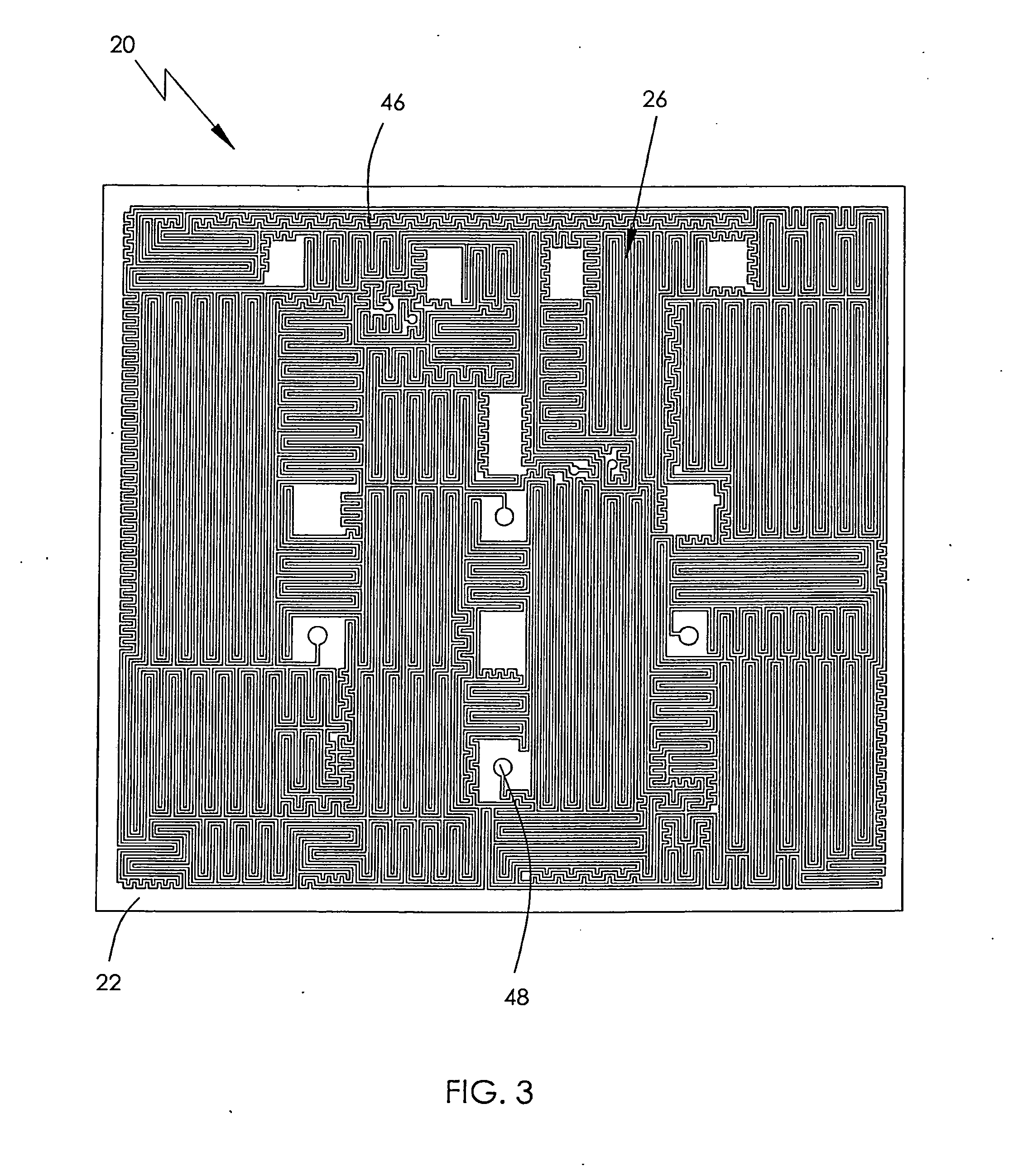
[0056]FIG. 2 shows the security wrap 20 as an open face version covering a large portion of the PCB 16 of the POS device. The PCB 16 forms a parent device to be protected and the security wrap 20 is bonded to the PCB 16. The reverse side of the security wrap 20 is shown in FIG. 3 which illustrates the complete security wrap of FIG. 2 rea...


PUM


Abstract

A security wrap (20) for protecting an electronic component includes a substrate (22) having a first side and a second side opposite to each other. A security screen (26) is disposed over the first side of the substrate (22) and includes a pair of screen terminals (48) and a frangible and electrically conductive path (46) between the pair of screen terminals (48). A layer of adhesive (30) is over the first side of the substrate (22) and bonds the first side of the substrate (22) to the electronic component with the security screen (26) sandwiched there between.

Description

CROSS REFERENCE TO RELATED APPLICATIONS[0001]This non-provisional patent application claims priority under 35 U.S.C. §119(a) from Patent Application No. 1213442.5 filed in United Kingdom on Jul. 27, 2012.FIELD OF THE INVENTION[0002]This invention relates to a tamper detection device and in particular to a flexible security wrap for an electronic circuit used to detect invasive tampering.[0003]Although this invention will be described in relation to security wraps as an example of the invention, the invention can be used with any printed electronics (PE) flex requiring a need for detection of removal or tampering.BACKGROUND OF THE INVENTION[0004]Currently, security wraps form a solid security screen masking an area of the electronics to be protected. Removal of the security wrap is physically difficult due to the manner in which the security wrap is attached to the device, usually by gluing, soldering or encapsulation with a resin material. However, they offer little in the way of ta...

Claims


Application Information

Patent Timeline
IPC IPC(8): G08B13/12
CPCG08B13/12G06F21/87G08B13/128H05K1/0275H05K2201/09263G06F21/86G09F3/03G09F3/0329H01L23/57
Inventor SALLE, VINCENT DANIEL JEANWARD, DOMINIC JOHNEDMONDS, MARTIN WALLACEZHANG, LIBING
Owner JOHNSON ELECTRIC SA
Why Eureka
Try Eureka