Microscope and method for operating a microscope

a microscope and microscope technology, applied in the field of microscopes and microscopes, can solve the problems of limited image-recording of living cells, limited number of possible image-recordings, and often reached limits, so as to reduce the photobleaching of dyes, reduce the damage of photodetectors, and extend the dynamic range.

Active Publication Date: 2014-01-30
CARL ZEISS MICROSCOPY GMBH
View PDF2 Cites 12 Cited by
  • Summary
  • Abstract
  • Description
  • Claims
  • Application Information

AI Technical Summary

Benefits of technology

[0013]The present invention provides a microscope and a method for operating a microscope which involve extension of the dynamic range and reduction of photodamage in the specimens being examined, more particularly living cells, and reduction of the photobleaching of dyes.

Problems solved by technology

The dynamic range of present-day photodetectors is, particularly in laser-scanning microscopy, frequently insufficient for simultaneous resolution, with equal sensitivity, of very fine and dark structures on the one hand and very light image areas on the other hand.
Furthermore, the photodamage caused in cells and tissue by intense illumination is to date one of the key factors that significantly limits the number of possible image-recordings of living cells and thus the measurement time, cf.
In the field of laser-scanning microscopy, limits are often reached as far as minimization of photobleaching effects and optimization of the level control in the detector are concerned.
However, dynamic depths of 16 bits have hardly ever been achieved for microscopic purposes.
Highly sensitive CCD cameras having an extremely large dynamic range are scarcely used in laser-scanning microscopy on account of light scatter.
The disadvantage of this method is not only the significantly greater stress on the specimen but also the recording time required.
This method is either not possible or at least not optimal for many applications, particularly those involving measurements performed on living cells.
Secondly, photodamage also takes place as a result of excitation of the dye itself, which decomposes to toxic products after a certain number of excitation cycles.
In the DIM method, the dynamic range is reduced on the excitation side due to nonlinearity problems involving the square root.
In order to resolve fine structures using the CLEM method, the constant laser power used for the entire image must be optimized for the darkest portions, which results in the light portions of the image experiencing extremely short exposure times at a high illumination intensity.
However, this results in significantly greater photodamage.
In the normal case, the emission spectra of the available dyes are not sufficiently different to make it possible to completely prevent crosstalk by means of filter combinations, without involving an extremely large loss of light.
But since the contribution of individual dyes to the brightness in the different channels fluctuates strongly due to the concentration distributions between the individual pixels in many applications, the adjustment of the detection channels is not optimal for most pixels.
This results in a larger signal to noise ratio of the individual pixels of the spectrally unmixed images.
Readjustment is thus carried out, as in the method described above, but the algorithm for readjustment is more complicated since the intensity regulation of a wavelength does not exclusively influence the contribution of a single dye but possibly the contributions of several dyes to different extents.

Method used


Image

  • Microscope and method for operating a microscope
  • Microscope and method for operating a microscope
  • Microscope and method for operating a microscope

Examples


Embodiment Construction

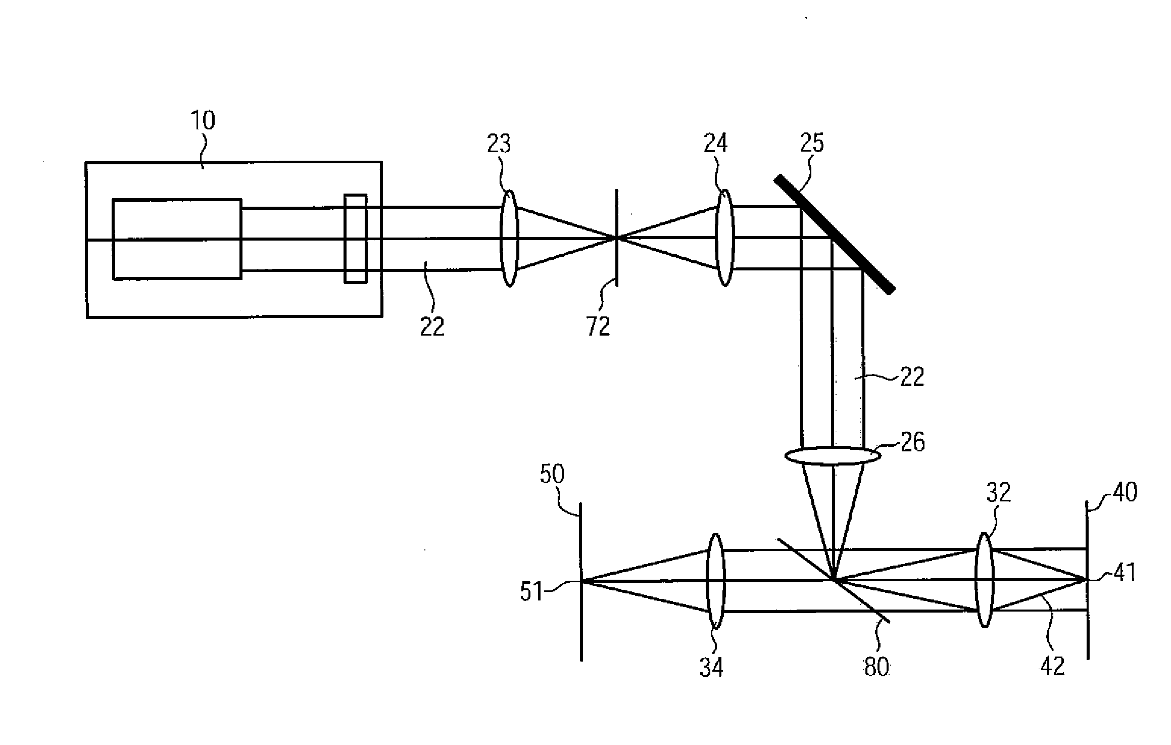
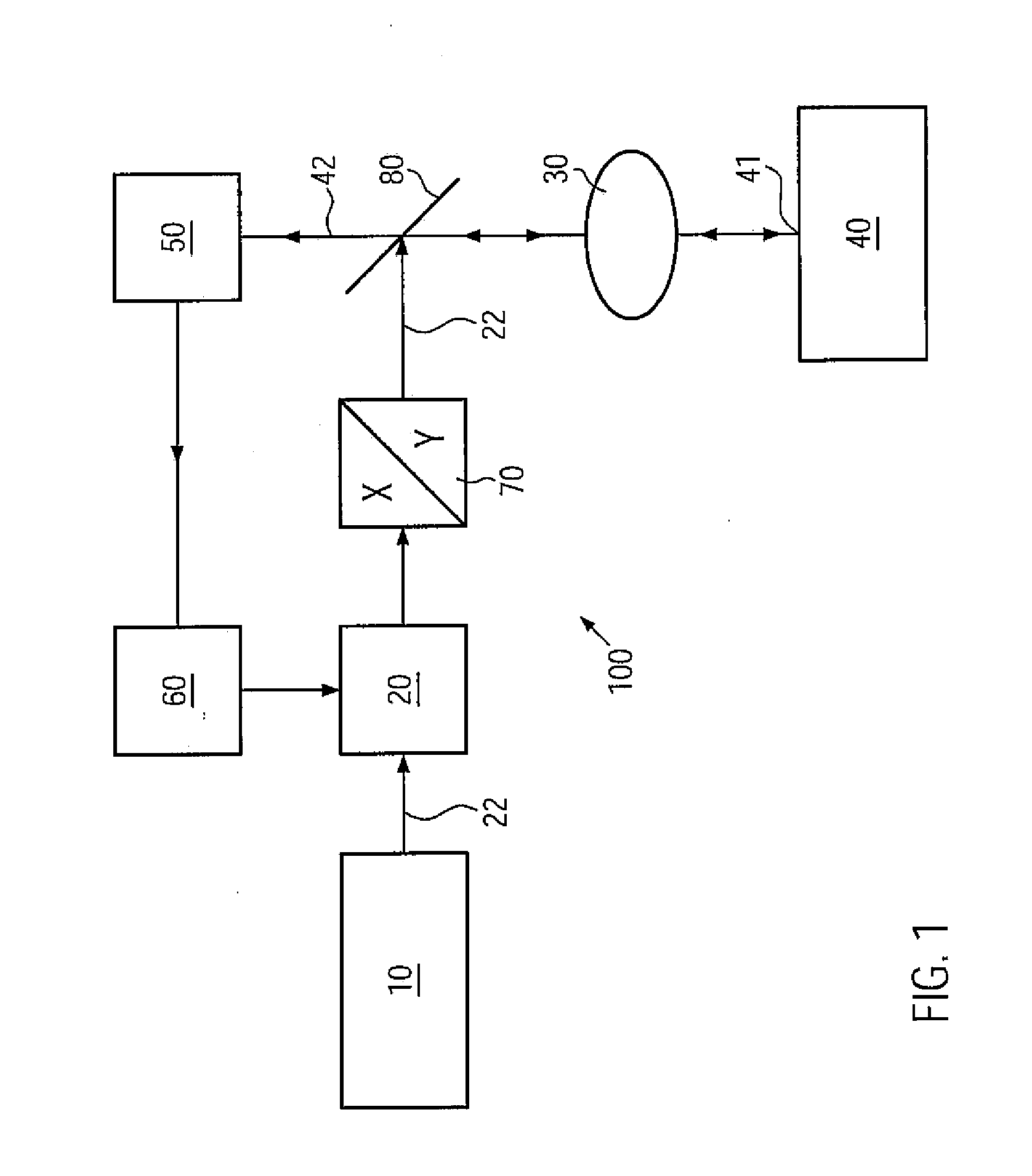
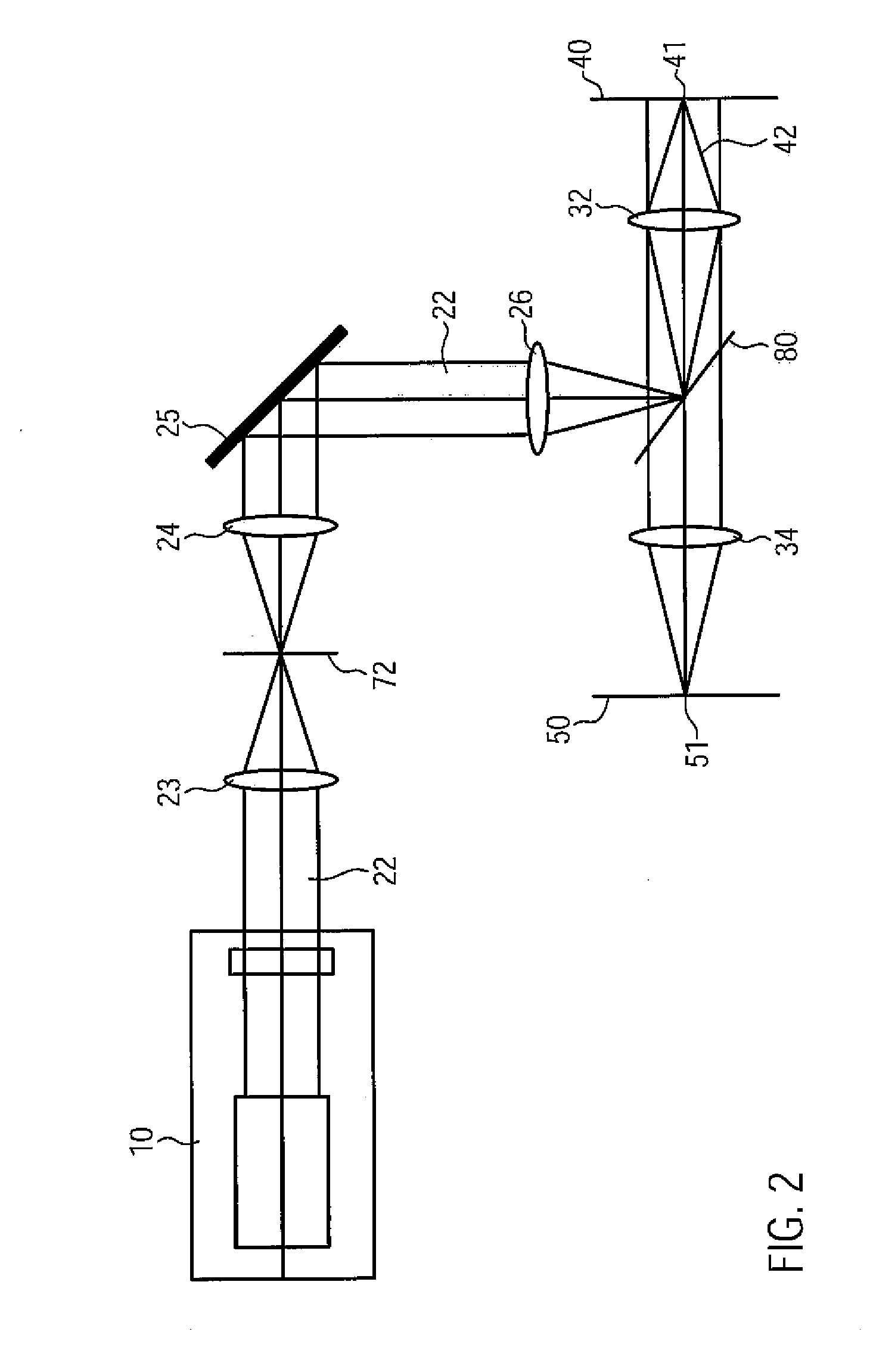
[0079]The structure of a microscope of the invention and the elementary sequences of the method of the invention are explained below with reference to FIGS. 1 and 7. Additional exemplary embodiments are then explained with reference to FIGS. 2 to 6 and 8. Equivalent components in the figures are provided with the same reference signs.

[0080]The microscope 100 of the invention shown diagrammatically in FIG. 1 is a point-scanning microscope. The microscope 100 includes a light source 10 such as a laser, an intensity modulator 20, a scanning device 70, a microscope optics 30, a detector 50 and a regulating device 60. The light source 10 emits excitation light 22 for the microscopic examination of a specimen 40. An intensity of the excitation light 22 is selectively adjusted, according to the invention, with the aid of the intensity modulator 20. The excitation light 22 reaches a point 41 of the specimen by way of the scanning device 70, a main beam splitter 80 and the diagrammatically i...


PUM


Abstract

The invention relates to a method for operating a microscope in which excitation light is focused on, or beamed to, different points of a specimen, in which an intensity of the excitation light is point-specifically varied and in which an intensity of the light reflected by said specimen in at least one spectral range is measured point-specifically and quantitatively. The method according to the invention is characterized in that the intensity and/or a spectral composition of the excitation light beamed to a specific point of said specimen is automatically adjusted by a regulating device on the basis of information previously gained from measured data of said specimen concerning an estimated or actual intensity of the light reflected in the spectral range by said point such that an integral of the intensity of the light reflected in the spectral range by this point during a pixel dwell time is within a predefined value interval. The invention also relates to a microscope.

Description

REFERENCE TO PRIOR APPLICATIONS[0001]The current application is a Continuation application of U.S. Utility application Ser. No. 12 / 679,967, which was filed on 7 Apr. 2010, which is hereby incorporated by reference.TECHNICAL FIELD[0002]The present invention relates, in a first aspect, to a method for operating a microscope and to a microscope.RELATED ART[0003]A generic method and a generic microscope are disclosed in EP 0 977 069 B1, for example. In a method of the type mentioned above, excitation light is focused on, or beamed to, different points of a specimen, and an intensity of the excitation light is varied point-specifically, and an intensity of light reflected by the specimen is measured in at least one spectral range point-specifically and quantitatively.[0004]A generic microscope comprises the following components: a light source for emitting excitation light for the microscopic examination of a specimen, an intensity modulator for varying an intensity of the excitation lig...

Claims


Application Information

Patent Timeline
Patent Type & Authority Applications(United States)
IPC IPC(8): G02B21/06
CPCG02B21/06G02B21/0076
Inventor KLEPPE, INGOLIEDTKE, MIRKO
Owner CARL ZEISS MICROSCOPY GMBH
Why Eureka
Try Eureka