
Wireless communication system, wireless communication method, and mobile terminal

a wireless communication and wireless communication technology, applied in the field of wireless communication technology, can solve the problems of not always supporting the function of a wireless access system with a wireless access system, the function may not be used, and the changeover takes time, so as to shorten the time necessary

Inactive Publication Date: 2014-01-30
HITACHI LTD
View PDF2 Cites 28 Cited by
  • Summary
  • Abstract
  • Description
  • Claims
  • Application Information

AI Technical Summary

Benefits of technology

The present invention provides a solution for a network with multiple wireless access systems. The invention allows devices in the core network of a first wireless access system to serve as base stations for both the first and second wireless access systems. This improves the handover process between access systems and ensures seamless services regardless of the access system used. This invention reduces the time required for handovers and provides seamless services to mobile users.

Problems solved by technology

Therefore, in the case of performing handover necessary to change over to a different access system, there is a problem in that it takes time for a changeover.
Therefore, a function supported by a wireless access system is not always supported by another wireless access system.
This means that a function can be used before handover between wireless access systems but the function may not be used after handover between the wireless access systems.
As described above, when handover occurs between different access systems, problems arise in that functional difference occurs between the wireless access systems and it is difficult to seamlessly provide services.

Method used


Image

  • Wireless communication system, wireless communication method, and mobile terminal
  • Wireless communication system, wireless communication method, and mobile terminal
  • Wireless communication system, wireless communication method, and mobile terminal

Examples


Embodiment Construction

[0021]In the following, an embodiment of the present invention will be described with reference to the drawings.

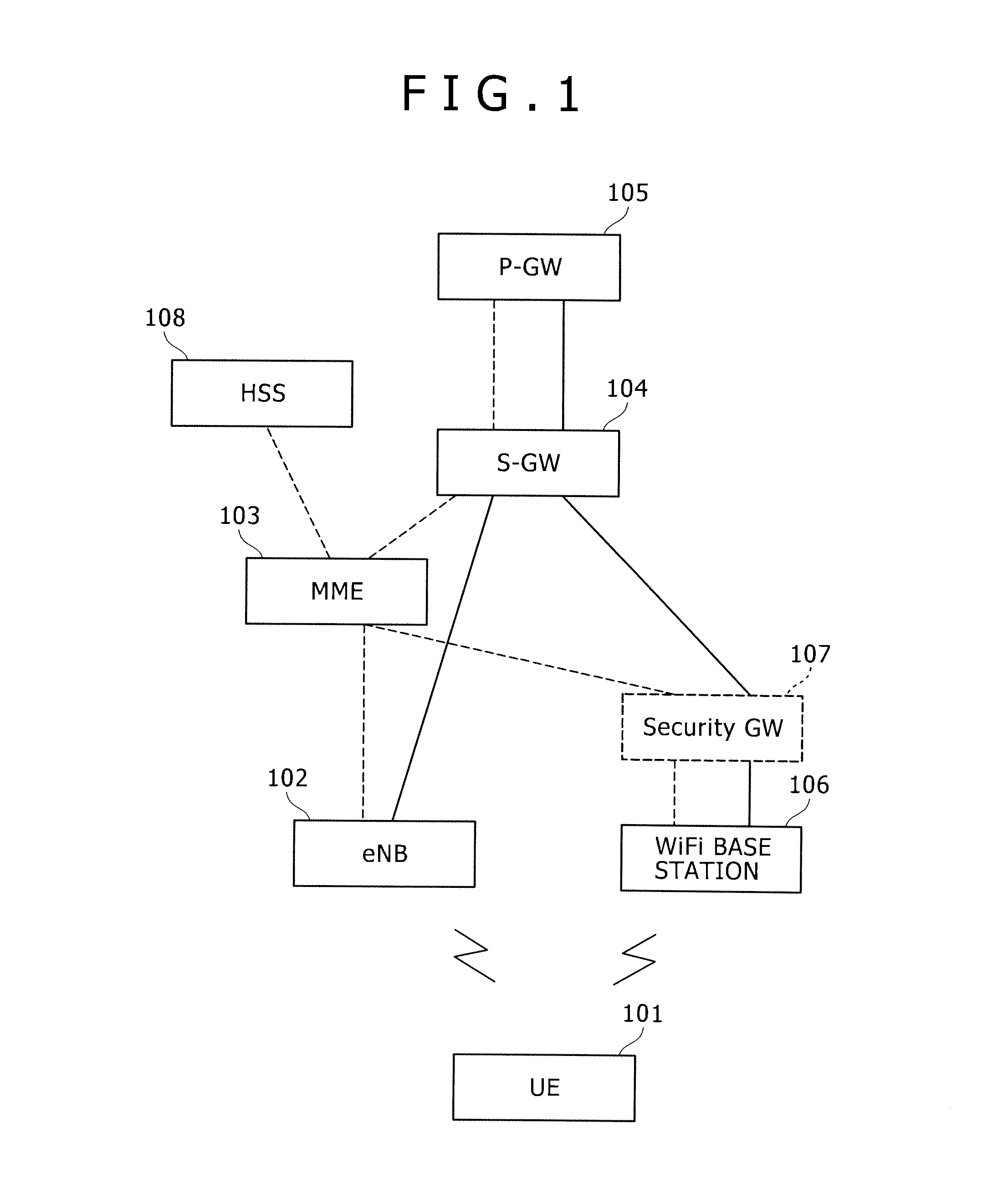
[0022]In the following embodiment, an eNB, which is an LTE base station, is taken as an example as a macro base station, and a WiFi base station that supports IEEE 802.11 is taken as an example of a wireless LAN base station. An embodiment is shown and described in which two wireless access systems cover areas.

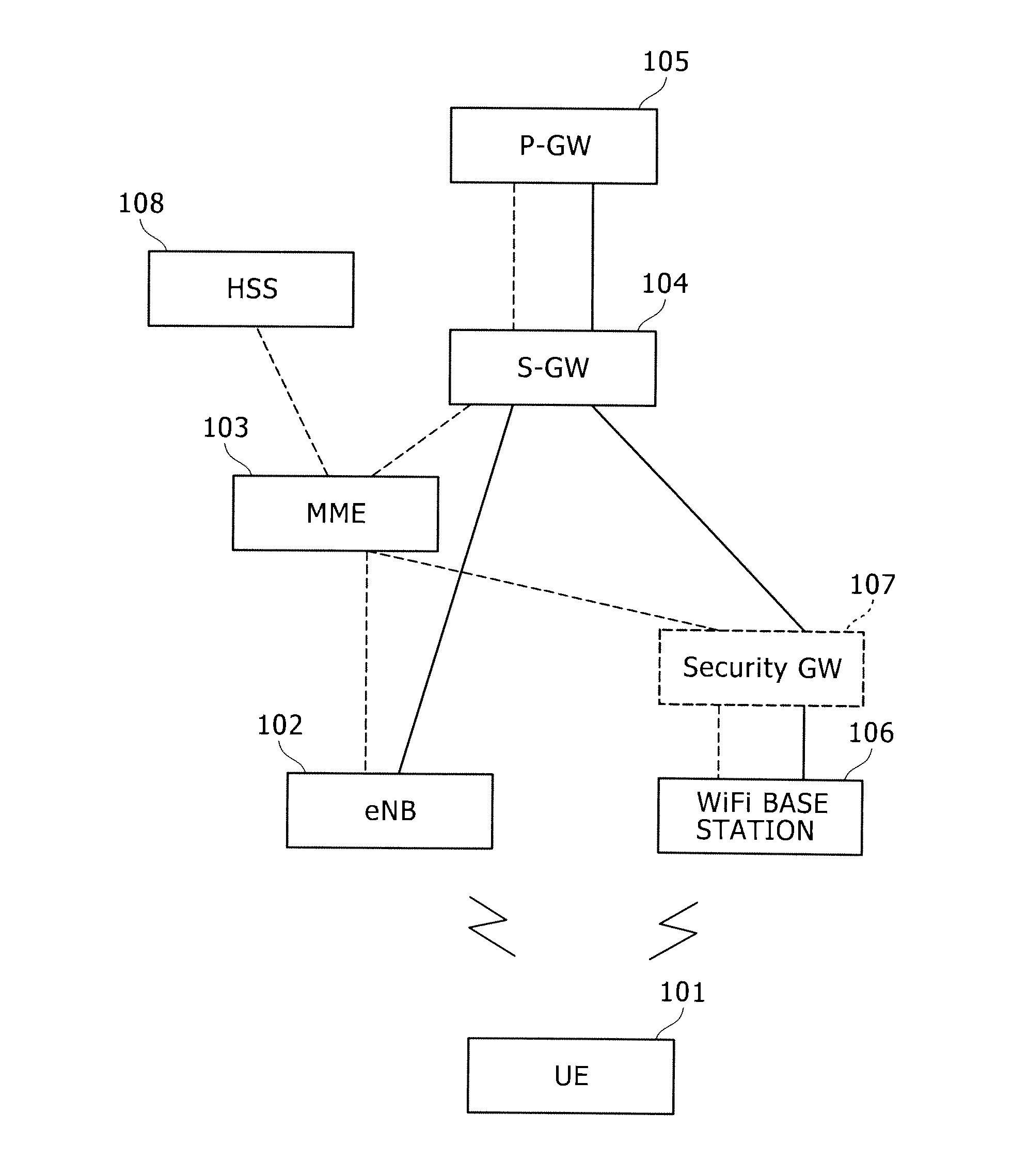
[0023]FIG. 1 is a diagram of the configuration of a wireless communication system according to an embodiment of the present invention.

[0024]FIG. 1 is a wireless communication system to which LTE wireless access and WiFi wireless access are applied as wireless access technologies.

[0025]First, the case will be described where a UE 101 performs call establishment via an eNB 102 according to an LTE wireless mode.

[0026]The UE 101 first calls and connects to the eNB 102 according to the procedures stipulated in the LTE standard. A call establishment control signal sent fro...


PUM


Abstract

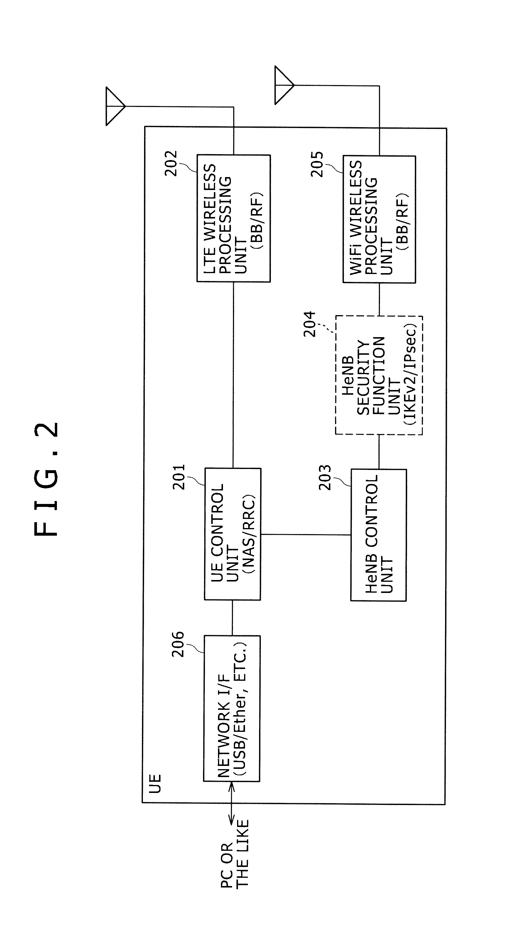
A mobile terminal includes: an LTE wireless processing unit having an LTE communication function; a wireless LAN processing unit having a wireless LAN communication function; and a terminal control unit that determines whether to use the LTE wireless processing unit or the wireless LAN processing unit and controls a function as a wireless terminal. The mobile terminal includes a base station functional unit having a communication protocol processing function of an LTE base station. Based on control of the terminal control unit, a signal generated at the base station functional unit, the signal being based on the communication protocol of the LTE base station, is stored in a wireless LAN frame, and the signal is sent to a device in the LTE core network via a wireless LAN base station.

Description

FIELD OF THE INVENTION[0001]The present invention relates to a wireless communication technique and more particularly to a wireless communication technique in a wireless communication system including mobile terminals having functions to communicate with a plurality of wireless access systems.BACKGROUND OF THE INVENTION[0002]In wireless communication systems, the coverage (the cell) of a base station generally called a macro base station ranges from a radius of a few hundred meters to a radius of dozens or so kilometers. Mobile network operator provide macro base stations so as to cover areas to which wireless communication services are provided. However, areas where radio waves from a base station do not tend to be delivered are generated such as indoor spaces and cell boundaries. The mobile network operator provide wireless LAN base stations at some spots in order to enable communications also in such areas where radio waves do not tend to be delivered. The coverage of the wireles...

Claims


Application Information

Patent Timeline
Patent Type & Authority Applications(United States)
IPC IPC(8): H04W36/00
CPCH04W36/0005H04W88/06H04W36/0066H04W84/12H04L63/0471H04W12/06H04W36/0038H04W12/03
Inventor TAKAHASHI, YOSUKEYOSHIDA, AKIHIKO
Owner HITACHI LTD
Learn More