Locating device for slide joint

a technology for locating devices and slide joints, which is applied in the direction of couplings, rod connections, manufacturing tools, etc., can solve the problems of short service life, lock devices, and the error movement of pushbutton to lose the function of automatic locating of inner pipes, so as to reduce the manufacturing cost of locating devices and facilitate assembly and quick

Inactive Publication Date: 2014-01-30
LEE YU CHIEH
View PDF12 Cites 43 Cited by
  • Summary
  • Abstract
  • Description
  • Claims
  • Application Information

AI Technical Summary

Benefits of technology

[0013]With the above arrangements, the locating device for slide joint according to the present invention provides the beneficiary effect that the engaging section of the pushbutton, due to the torque of the torsion spring, automatically presses against the inner annular rib for the inner end of the locating rod to extend through the through hole on the outer member and insert into one locating hole on the inner member without the drawbacks of the prior art locating device for slide joint. The locating device of the present invention also has the following advantages: (1) since the pushbutton acts on the locating rod by pressing the engaging section against the annular ribs on the locating rod, the pushbutton and the locating rod can be separately fabricated and then easily and quickly assembled to each other to reduce the manufacturing cost of the locating device; and (2) the use of the torsion spring can produce constant rotational torque, which enables accurate and reliable automatic alignment of the locating rod with the through hole and locating hole to avoid the risk of failing to lock the outer and inner members together by the locating rod due to changed direction of the elastic force. And, since the edge of the opening of the engaging section communicates with the end surface of the pushbutton and can be selectively pressed against the inner annular rib or pushed against the outer annular rib, the locating device can be quickly and reliably assembled.

Problems solved by technology

The above locking device has the following drawbacks: (1) since the pushbutton is pivotally connected at an end to the locating pin, the locking device could not be conveniently assembled and has short service life; and (2) with the other end of the pushbutton pressed against the return spring, the return spring tends to displace during the use of the locking device; and the displaced return spring will change the direction of its spring force to thereby possibly cause error movement of the pushbutton to lose the function of automatic locating of the inner pipe to the outer pipe.

Method used


Image

  • Locating device for slide joint
  • Locating device for slide joint
  • Locating device for slide joint

Examples


first embodiment

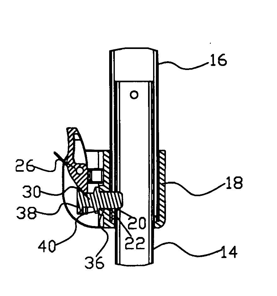
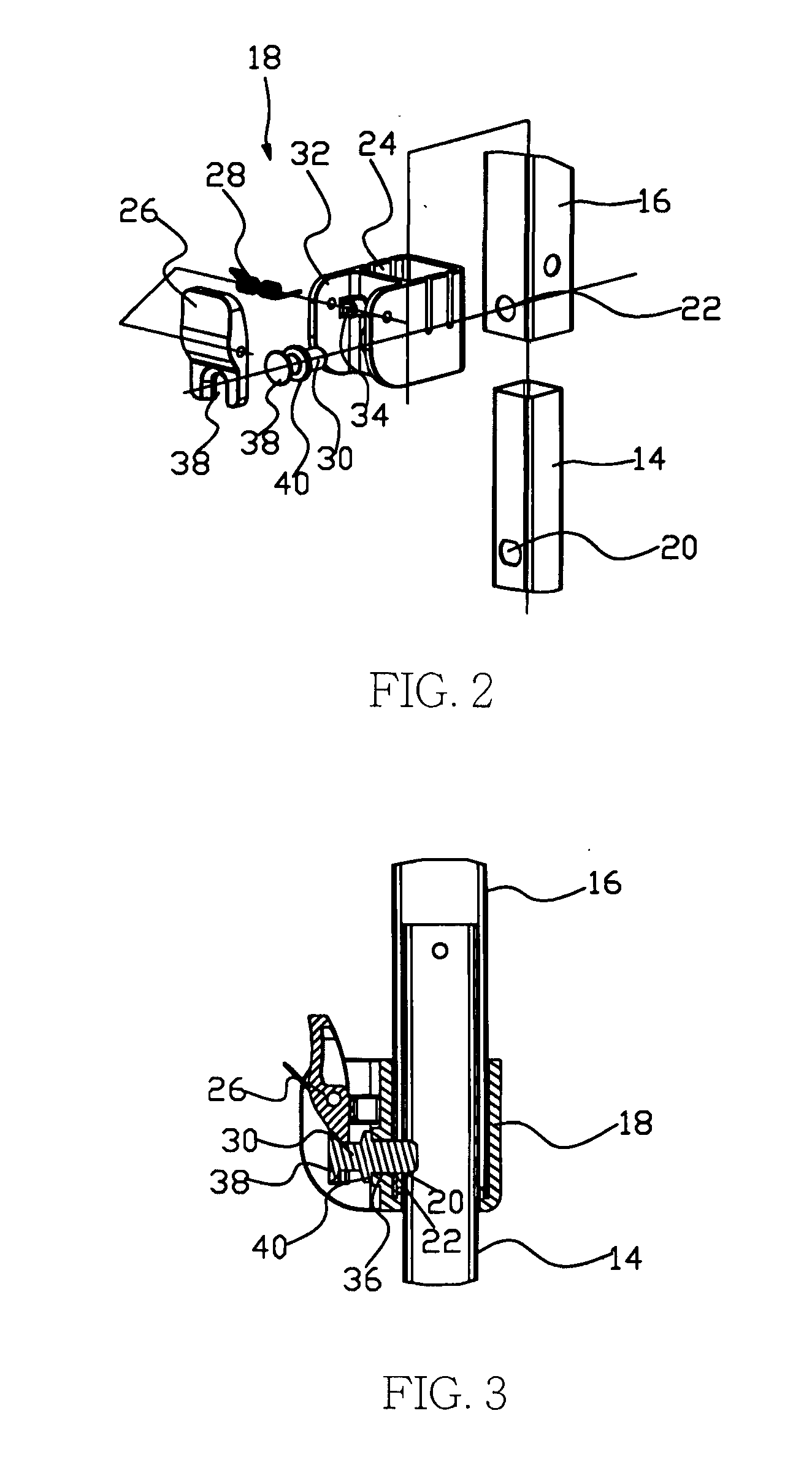
[0027]As can be seen in FIGS. 2 and 3, the locating device 18 for use with the telescopic pole 10 includes a mounting seat 24, a pushbutton 26, a torsion spring 28, and a locating rod 30.

[0028]The mounting seat 24 is fixedly mounted to an outer side of the outer pipe 16; and includes two forward extended lugs 32, two insertion holes 34, and a through hole 36.

[0029]The pushbutton 26 has a middle section located in between the two lugs 32 of the mounting seat 24. A pivot shaft (not shown) is extended through the two lugs 32 and the middle section of the pushbutton 26, so that the pushbutton 26 is pivotally connected to the mounting seat 24 via the pivot shaft. The pushbutton 26 further includes an engaging section 38 located at an end thereof. The engaging section 38 defines an opening communicating with the end surface of the pushbutton 26.

[0030]The torsion spring 28 is fitted around the pivot shaft with two ends separately inserted in the two insertion holes 34, which are provided o...

second embodiment

[0035]FIG. 4 shows a folding bed frame that can be converted into a sofa according to actual need. Chinese Utility Patent entitled “Sofa-convertible Folding Bed and Bed Frame Thereof” granted to the same applicant can be referred to for the detailed description of the structure of the folding bed frame. The folding bed frame includes a foldable support frame 10 and four backrest poles 12 spaced along a longitudinal direction of the support frame 10. Please also refer to FIGS. 5 and 6. Each of the backrest poles 12 has a connector provided thereon. The connector includes a first slidable joint 42 and a second slidable joint 16, which are pivotally connected to each other. The backrest pole 12 has a lower end pivotally connected to a lower portion of a first pipe of a rear scissor linkage, and an upper end slidably extended through the first slidable joint 42. The second slidable joint 16 is slidably fitted on around an upper portion of a second pipe 14 of the rear scissor linkage. A ...

third embodiment

[0043]FIG. 7 shows a foldable table frame that includes a base frame 10, a table top frame 44, and two spaced sets of scissor linkages 12 separately connected to between the base frame 10 and the table top frame 44. Each set of scissor linkages 12 includes multiple serially pivotally connected scissor linkages. One of the two lowermost ends of each set of scissor linkages 12 is pivotally connected to the base frame 10, while the other lowermost end is slidably connected to the base frame 10. One of the two uppermost ends of each set of scissor linkages 12 is pivotally connected to the table top frame 44, while the other uppermost end is provided with a slidable joint 16. The slidable joint 16 is slidably connected to a side pipe 14 of the table top frame 44. A locating device 18 according to the present invention is connected to between the slidable joint 16 and the side pipe 14. When the locating device 18 is in a locked position, the slidable joint 16 is immovably connected to the...


PUM


Abstract

A locating device for slide joint is mounted to an inner member provided with at least one locating hole and an outer member provided with a through hole and slidably fitted on the inner member. The locating device includes a mounting seat mounted on the outer member; a pushbutton pivotally connected to the mounting seat and having an engaging section located at an end thereof; a torsion spring arranged between the pushbutton and the mounting seat to apply a constant torque on the pushbutton; and a locating rod having two spaced annular ribs. The engaging section of the pushbutton is located between the two annular ribs to selectively press against one of the two inner annular ribs under the torque of the torsion spring. The locating rod has an inner end extended through the through hole on the outer member to insert into the locating hole on the inner member.

Description

FIELD OF THE INVENTION[0001]The present invention relates to a locating device for slide joint.BACKGROUND OF THE INVENTION[0002]A locating device can be used to releasably lock two slidably connected members in a variety of applications, such as being used on a telescopic pipe or between a pipe and a sliding sleeve mounted on around the pipe. The conventional locking device for the telescopic pole of tent frame includes an inner pipe and an outer pipe, both of which have a locating hole formed thereon. A locating seat is fixedly mounted on around the outer pipe, and a pushbutton is pivotally connected at a middle section to the locating seat. The pushbutton has an end provided with a locating pin, and another end pressed against a return spring. The locating pin is aligned with the locating hole on the outer pipe. To deploy the tent frame, first pull the inner pipe from the outer pipe. When the locating pin is also aligned with the locating hole on the inner pipe, the return spring ...

Claims


Application Information

Patent Timeline
Patent Type & Authority Applications(United States)
IPC IPC(8): F16B21/00
CPCF16B7/105E04H15/50Y10T403/60
Inventor LEE, YU CHIEH
Owner LEE YU CHIEH
Why Eureka
Try Eureka