Cardiac implant configured to receive a percutaneous prosthetic heart valve implantation

a prosthetic heart valve and cardiac implant technology, applied in the field of prosthetic cardiac implants, can solve the problems of inability to properly repair the native heart valve that was successfully repaired using an annuloplasty ring, the valve disease can be severe and even fatal, and the backflow of blood through the valve is excessive, so as to improve the deployment of the prosthetic valve

Active Publication Date: 2014-01-30
EDWARDS LIFESCIENCES CORP
View PDF2 Cites 35 Cited by
  • Summary
  • Abstract
  • Description
  • Claims
  • Application Information

AI Technical Summary

Benefits of technology

[0017]The invention is a prosthetic heart valve and an annuloplasty ring configured to receive a prosthetic heart valve, such as a catheter-deployed (transcatheter) prosthetic heart valve, therein. In one embodiment, the prosthetic heart valve has a support structure which is generally resistant to expansion when deployed in the patient's native heart valve annulus to replace the native heart valve (or to replace another prosthetic heart valve), but is configured to transform to a generally expanded and / or expandable configuration in order to receive a prosthetic heart valve therein. In another embodiment, the annuloplasty ring has a generally non-circular shape when deployed in the patient's native heart valve to correct heart valve function, but is configured to assume a generally circular configuration when subjected to a dilation force such as that provided by a dilation balloon used to deploy a prosthetic valve. The annuloplasty ring or prosthetic heart valve of the invention can be deployed using various surgical techniques (e.g., traditional open-chest, minimally-invasive, percutaneous, etc.) to correct heart valve function, and the expandable prosthetic valve can be deployed within the same native valve annulus at a much later time. The annuloplasty ring is configured to accept and even improve deployment of the prosthetic valve within the native valve annulus. The transformation from expansion-resistant to expanded / expandable, and / or from generally non-circular shape to generally circular configuration, can be achieved by subjecting the heart valve or annuloplasty ring support structure to an outward force, such as a dilation force, which may be provided by a dilation balloon used to deploy a replacement prosthetic valve.
[0018]The prosthetic heart valve structure may be generally rigid prior to dilation, and may be configured to become generally non-rigid, and even generally elastic, when subjected to an outward force. The elasticity may assist in holding a percutaneously-introduced prosthetic valve within the current prosthetic valve structure.
[0021]A prosthetic valve according to an embodiment of the invention may include a cover configured to hold the core together after it has been dilated. For example, where a core breaks into multiple pieces during dilation, the cover can serve to keep the pieces from separating from the prosthetic valve. The cover can also serve to hold the core and / or other portions of the support frame in a desired shape, and may have elastic properties.
[0022]In an embodiment of the invention, the prosthetic valve is a stented bioprosthetic valve configured to expand and contract dynamically within the patient's annulus. The dynamic motion of the annulus can enable the valve opening to expand during periods of peak demand, and reduce the annular restriction to the increased flow. The expansion can also decrease leaflet stresses associated with potential higher gradients. The expansion can also permit later placement of an expandable prosthetic valve within the stented bioprosthetic valve.

Problems solved by technology

Diseased heart valves may be categorized as either stenotic, wherein the valve does not open sufficiently to allow adequate forward flow of blood through the valve, and / or incompetent, wherein the valve does not close completely, causing excessive backward flow of blood through the valve when the valve is closed.
Valve disease can be severely debilitating and even fatal if left untreated.
For example, a native heart valve that was successfully repaired using an annuloplasty ring may suffer further damage years after the annuloplasty ring was implanted.
Similarly, a prosthetic heart that was successfully implanted to replace a native valve may itself suffer damage and / or wear and tear many years after initially being implanted.
Implanting the prosthetic heart valve directly within a previously-implanted prosthetic heart valve is generally impractical, in part because the new prosthetic heart valve (including the support structure and valve assembly) will have to reside within the annulus of the previously-implanted heart valve, and traditional prosthetic heart valves are not configured to easily receive such a valve-within-a-valve implantation in a manner which provides secure seating for the new valve while also having a large enough annulus within the new valve to support proper blood flow therethrough.
Implanting the prosthetic heart valve directly within a previously-implanted annuloplasty ring is also generally impractical, largely because most prosthetic heart valves have a generally circular shape whereas most annuloplasty rings are generally non-circular (including “D” and dog-bone shapes).
However, in cases where a previously-implanted prosthetic heart valve or annuloplasty ring is present, deploying a prosthetic heart valve within the native heart valve annulus may be impractical.
The shape and structure of the previously-installed prosthetic heart valve or annuloplasty ring may interfere with the proper placement, deployment, and functioning of the new prosthetic heart valve.

Method used


Image

  • Cardiac implant configured to receive a percutaneous prosthetic heart valve implantation
  • Cardiac implant configured to receive a percutaneous prosthetic heart valve implantation
  • Cardiac implant configured to receive a percutaneous prosthetic heart valve implantation

Examples


Embodiment Construction

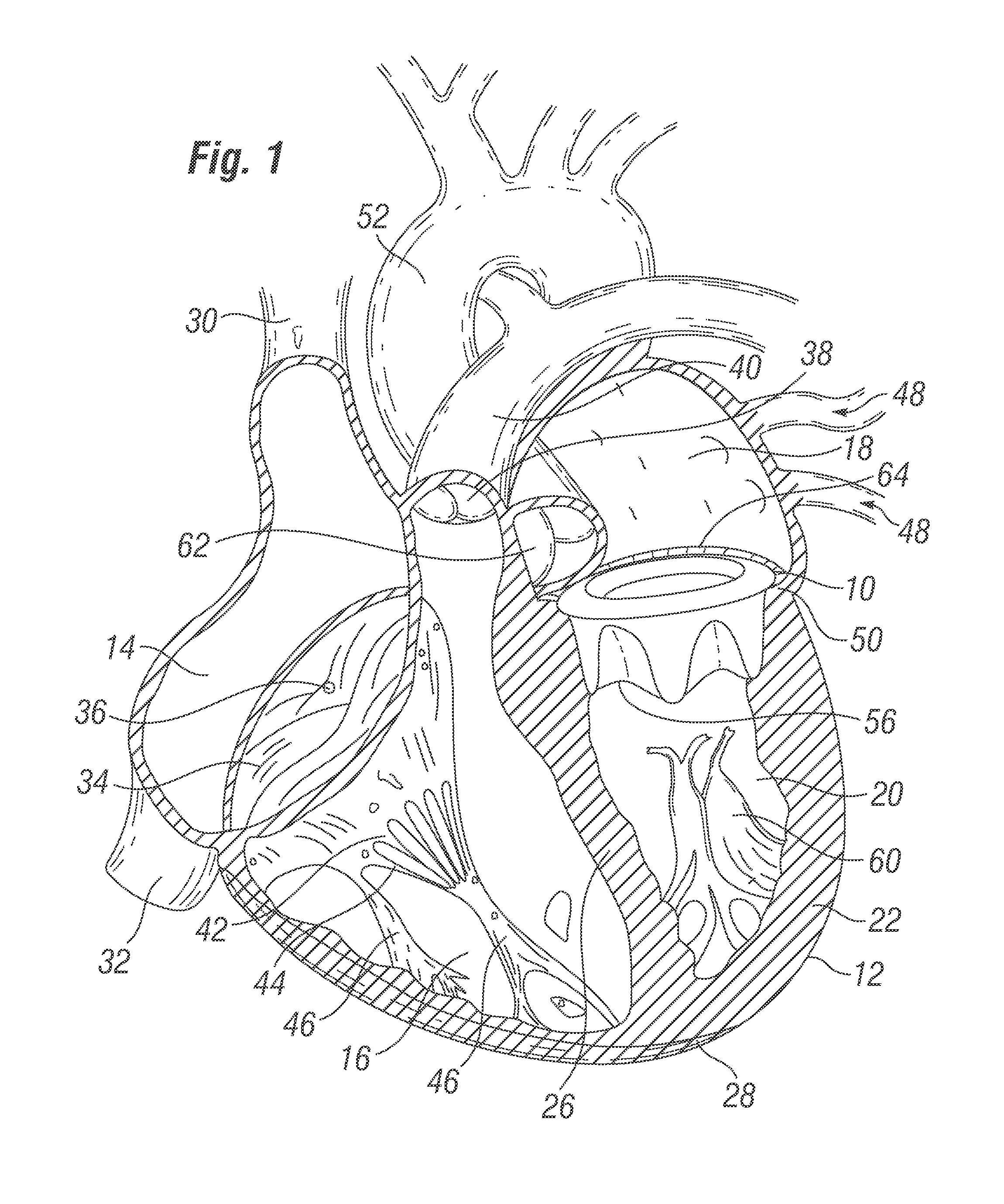
[0086]With reference to FIG. 1, a prosthetic heart valve 10 according to the invention is depicted in a heart 12. The heart 12 has four chambers, known as the right atrium 14, right ventricle 16, left atrium 18, and left ventricle 20. The general anatomy of the heart 12, which is depicted as viewed from the front of a patient, will be described for background purposes. The heart 12 has a muscular outer wall 22, with an interatrial septum 24 dividing the right atrium 14 and left atrium 18, and a muscular interventricular septum 26 dividing the right ventricle 16 and left ventricle 20. At the bottom end of the heart 12 is the apex 28.

[0087]Blood flows through the superior vena cava 30 and the inferior vena cava 32 into the right atrium 14 of the heart 12. The tricuspid valve 34, which has three leaflets 36, controls blood flow between the right atrium 14 and the right ventricle 16. The tricuspid valve 34 is closed when blood is pumped out from the right ventricle 16 through the pulmon...


PUM


Abstract

The invention is a cardiac implant, and associated methods therefore, configured to repair and / or replace a native heart valve, and having a support frame configured to be reshaped into an expanded / changed form in order to receive and / or support an expandable prosthetic heart valve therein. The implant may be configured to have a generally rigid and / or expansion-resistant configuration when initially implanted to replace / repair a native valve (or other prosthetic heart valve), but to assume a generally non-rigid and / or expanded / expandable form when subjected to an outward force such as that provided by a dilation balloon. The implant may be configured to have a generally D-shaped configuration when initially implanted, but to assume a generally circular form when subjected to an outward force such as that provided by a dilation balloon.

Description

CROSS REFERENCE TO RELATED PATENT APPLICATIONS[0001]The present application is a continuation of U.S. patent application Ser. No. 12 / 234,559, filed Sep. 19, 2008, entitled “Prosthetic Heart Valve Configured to Receive a Percutaneous Prosthetic Heart Valve Implantation,” the entire contents of which are incorporated herein by reference. The present application is also related to U.S. patent application Ser. No. 12 / 234,580, filed Sep. 19, 2008 and entitled “Annuloplasty Ring Configured to Receive a Percutaneous Prosthetic Heart Valve Implantation,” the entire contents of which are incorporated herein by reference.FIELD OF THE INVENTION[0002]The present invention relates to prosthetic cardiac implants for heart valve replacement and / or repair, and more particularly to a prosthetic heart valve and a prosthetic annuloplasty ring configured to receive an expandable prosthetic heart valve therein.BACKGROUND OF THE INVENTION[0003]In humans and other vertebrate animals, the heart is a hollow...

Claims


Application Information

Patent Timeline
Patent Type & Authority Applications(United States)
IPC IPC(8): A61F2/24
CPCA61F2/2442A61F2/2427A61F2/2433A61F2/958A61F2250/0071A61F2250/001A61F2/2418A61F2/2445A61F2220/0075A61F2230/0034A61F2/2412A61F2/2409
Inventor KEIDAR, YARONKONNO, MARK A.
Owner EDWARDS LIFESCIENCES CORP
Why Eureka
Try Eureka