Laser processing apparatus

a laser processing and laser beam technology, applied in metal working apparatus, manufacturing tools, welding/soldering/cutting articles, etc., can solve the problems of difficult to maintain the condition, difficult to set the laser beam focal point on the end surface of the core having a diameter of about 6 m, and difficult to set the laser beam focal poin

Active Publication Date: 2014-02-06
DISCO CORP
View PDF4 Cites 3 Cited by
  • Summary
  • Abstract
  • Description
  • Claims
  • Application Information

AI Technical Summary

Benefits of technology

[0008]It is therefore an object of the present invention to provide a laser processing apparatus having optical fiber means which can reliably set the focal point of the laser beam oscillated by the laser oscillator on the input surface (end surface) of the core of the optical fiber and can also maintain the condition that the focal point of the laser beam is set on the input surface of the core of the optical fiber.
[0012]According to the present invention, the optical transmitting means includes the focusing lens for focusing the laser beam oscillated by the laser oscillator and the optical fiber means for inputting the laser beam focused by the focusing lens and guiding it to the focusing means. The optical fiber means includes the LMA fiber for inputting the laser beam oscillated by the laser oscillator and focused by the focusing lens, the LMA fiber having a large-diameter core covered with a cladding, the transmitting fiber provided by an SM fiber or a PM fiber, the transmitting fiber having a small-diameter core covered with a cladding, the small-diameter core having a diameter corresponding to the wavelength of the laser beam oscillated by the laser oscillator, and the connecting means for connecting the LMA fiber and the transmitting fiber so that these fibers are axially aligned with each other. Accordingly, the focusing lens for focusing the laser beam oscillated by the laser oscillator is located so that the focal point of the laser beam focused by the focusing lens is set on the input surface of the core of the LMA fiber, wherein the diameter of this core is set to a relatively large value. Accordingly, the focal point of the laser beam can be easily set on the input surface of the core of the LMA fiber. Furthermore, it is possible to solve the problem that the focal point of the laser beam set on the input surface of the core of the LMA fiber may deviate from the input surface due to thermal expansion or strain.

Problems solved by technology

Accordingly, it is difficult to set the focal point of the laser beam oscillated by the laser oscillator on the end surface of the core of the optical fiber.
Furthermore, it is also difficult to maintain the condition that the focal point of the laser beam is set on the end surface of the core of the optical fiber.
In this case, it is difficult to set the focal point of the laser beam on the end surface of the core having a diameter of about 6 μm.
Furthermore, there is a problem such that the focal point of the laser beam may deviate from the end surface of the core of the optical fiber due to thermal expansion or strain after it is set on the end surface of the core of the optical fiber.

Method used


Image

  • Laser processing apparatus
  • Laser processing apparatus
  • Laser processing apparatus

Examples


Embodiment Construction

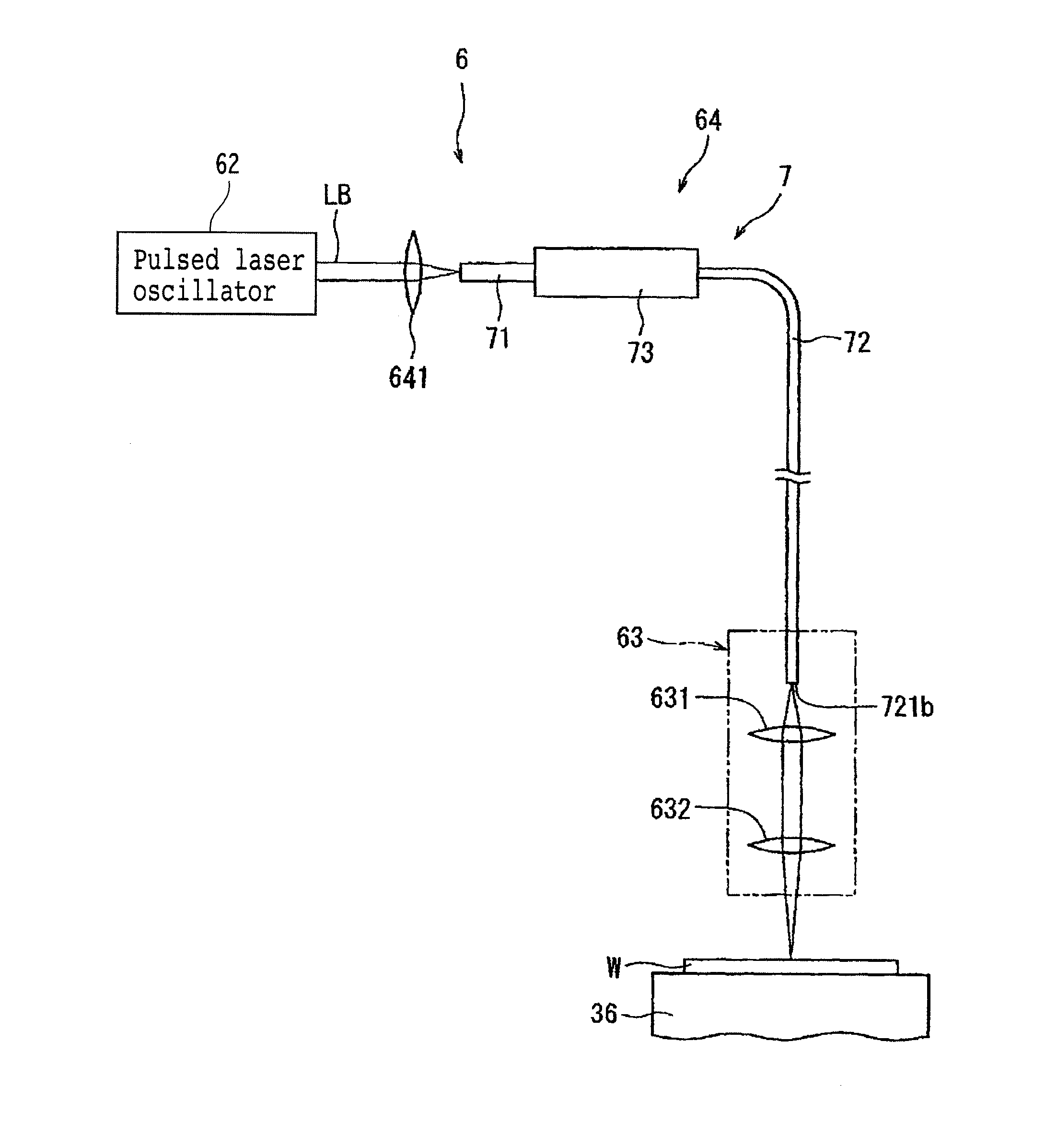
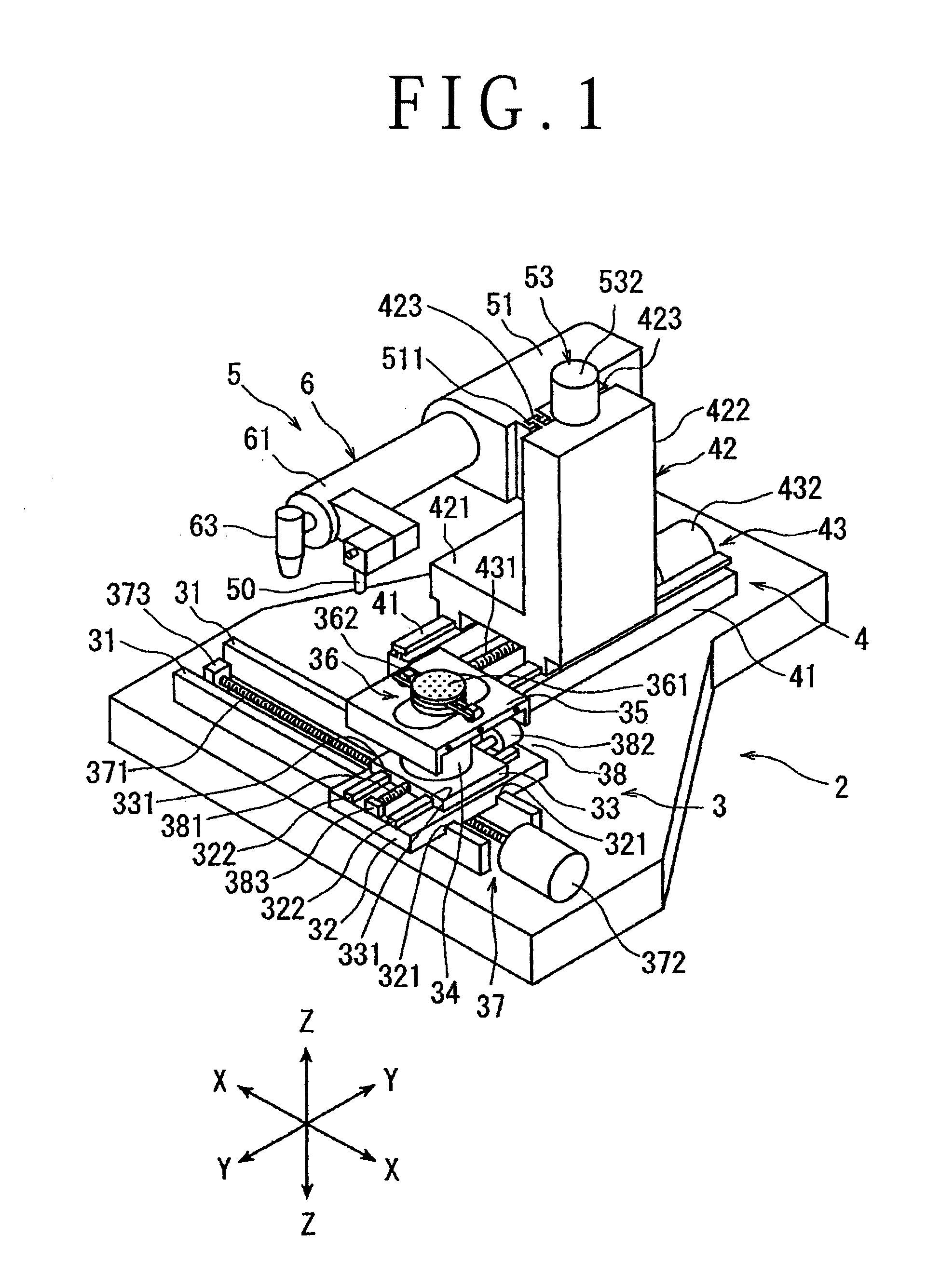
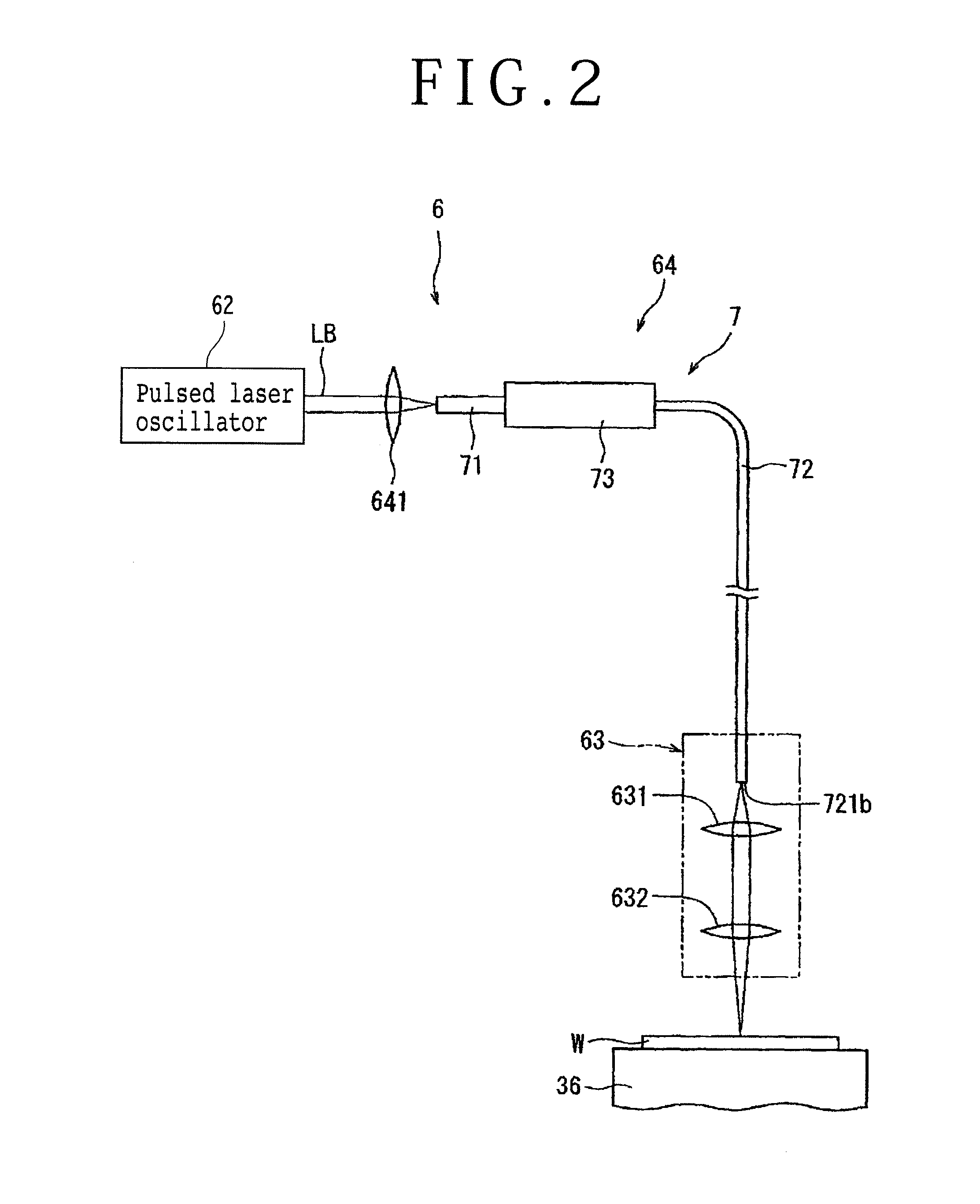
[0019]A preferred embodiment of the laser processing apparatus according to the present invention will now be described in detail with reference to the attached drawings. FIG. 1 is a perspective view of a laser processing apparatus according to a preferred embodiment of the present invention. The laser processing apparatus shown in FIG. 1 includes a stationary base 2, a chuck table mechanism 3 for holding a workpiece, the chuck table mechanism 3 being provided on the stationary base 2 so as to be movable in a feeding direction (X direction) shown by an arrow X, a laser beam applying unit supporting mechanism 4 provided on the stationary base 2 so as to be movable in an indexing direction (Y direction) shown by an arrow Y perpendicular to the X direction, and a laser beam applying unit 5 provided on the laser beam applying unit supporting mechanism 4 so as to be movable in a focal position adjusting direction (Z direction) shown by an arrow Z perpendicular to a holding surface of a c...


PUM

PropertyMeasurementUnit
diameteraaaaaaaaaa
diameteraaaaaaaaaa
diameteraaaaaaaaaa

Abstract

A laser processing apparatus has an optical transmitting unit for guiding a laser beam to a focusing unit. The optical transmitting unit includes a focusing lens for focusing the laser beam, an optical fiber unit for inputting the focused laser beam and guiding it to the focusing unit. The optical fiber unit includes an LMA fiber for inputting the focused laser beam. The LMA fiber has a large-diameter core covered with a cladding, a transmitting fiber provided by an SM fiber or a PM fiber. The transmitting fiber has a small-diameter core covered with a cladding, the small-diameter core having a diameter corresponding to the wavelength of the laser beam oscillated by the laser oscillator. A connector connects the LMA fiber and the transmitting fiber so that these fibers are axially aligned with each other.

Description

BACKGROUND OF THE INVENTION[0001]1. Field of the Invention[0002]The present invention relates to a laser processing apparatus for performing laser processing to a workpiece by applying a pulsed laser beam thereto.[0003]2. Description of the Related Art[0004]In a semiconductor device fabrication process, a plurality of crossing division lines called streets are formed on the front side of a substantially disk-shaped semiconductor wafer to thereby partition a plurality of regions where a plurality of devices such as ICs and LSIs are respectively formed. The semiconductor wafer is cut along the streets to thereby divide the regions where the devices are formed from each other, thus obtaining a plurality of individual semiconductor chips. Further, an optical device wafer is provided by forming a plurality of optical devices including photodetectors such as photodiodes and light emitting devices such as laser diodes on the front side of a sapphire substrate. The optical device wafer is a...

Claims


Application Information

Patent Timeline
Patent Type & Authority Applications(United States)
IPC IPC(8): B23K26/36B23K26/06
CPCB23K26/0648B23K26/367B23K26/364B23K2103/50B23K26/06B23K26/0861B23K26/0884B23K26/40B23K2101/40B23K26/0853B23K26/0869G02B6/32B23K26/36
Inventor NOMARU, KEIJI
Owner DISCO CORP
Why Eureka
Try Eureka