Switchgear Cabinet Arrangement of a Device for Producing Electric Energy

a technology of electrical energy and switch cabinet, which is applied in the direction of electric generator control, non-enclosed substations, substations, etc., can solve the problems of complicated cabling, complicated and costly plug-and-socket connections, and equipment efficiency drop, so as to simplify installation and scalability, the effect of reducing the number of connections and ensuring the effect of continuity

Active Publication Date: 2014-02-06
CONVERTERTEC DEUT GMBH
View PDF12 Cites 17 Cited by
  • Summary
  • Abstract
  • Description
  • Claims
  • Application Information

AI Technical Summary

Benefits of technology

[0007]The present invention is therefore based on the technical object of achieving an optimum scalability of devices for generating electrical energy with at the same time simple installation and maintenance of the power switch cabinets despite a small available installation space.

Problems solved by technology

However, with rotational speeds below the synchronous rotational speed of the generator the efficiency of the equipment drops.
Complicated and costly plug-and-socket connections are necessary to connect the power electronics part to the remainder of the frequency converter.
This requires a complicated cabling between the central CPU and the converter modules.
Furthermore, in the event of a defect the complete module has to be replaced.
The disadvantage in this case however is that the individual components of the frequency converter are distributed in various cabinets, which furthermore requires complicated cabling.
After the installation in the factory a subsequent scalability in situ is possible only with considerable effort and expenditure.
In addition the individual frame modules require a relatively large amount of space.

Method used


Image

  • Switchgear Cabinet Arrangement of a Device for Producing Electric Energy
  • Switchgear Cabinet Arrangement of a Device for Producing Electric Energy
  • Switchgear Cabinet Arrangement of a Device for Producing Electric Energy

Examples


Embodiment Construction

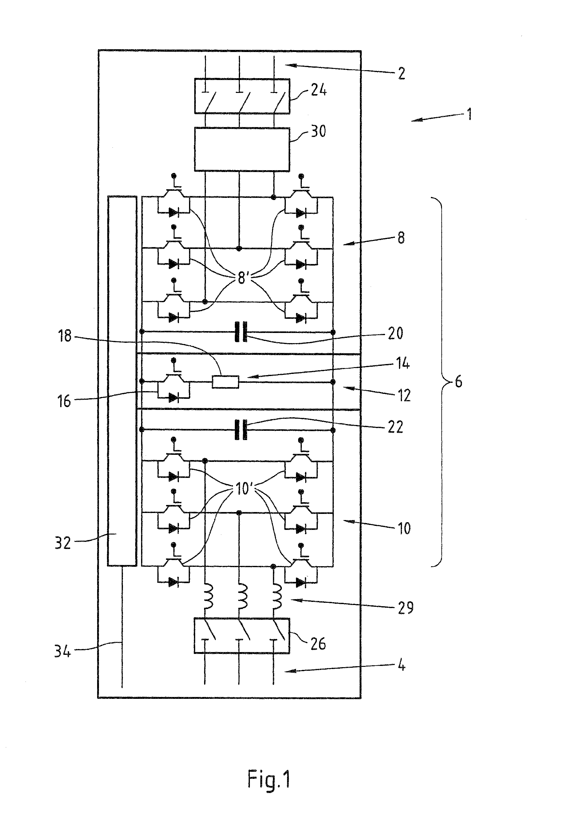
[0059]FIG. 1 shows schematically in the form of a circuit diagram the construction of an embodiment of a power switch cabinet 1.

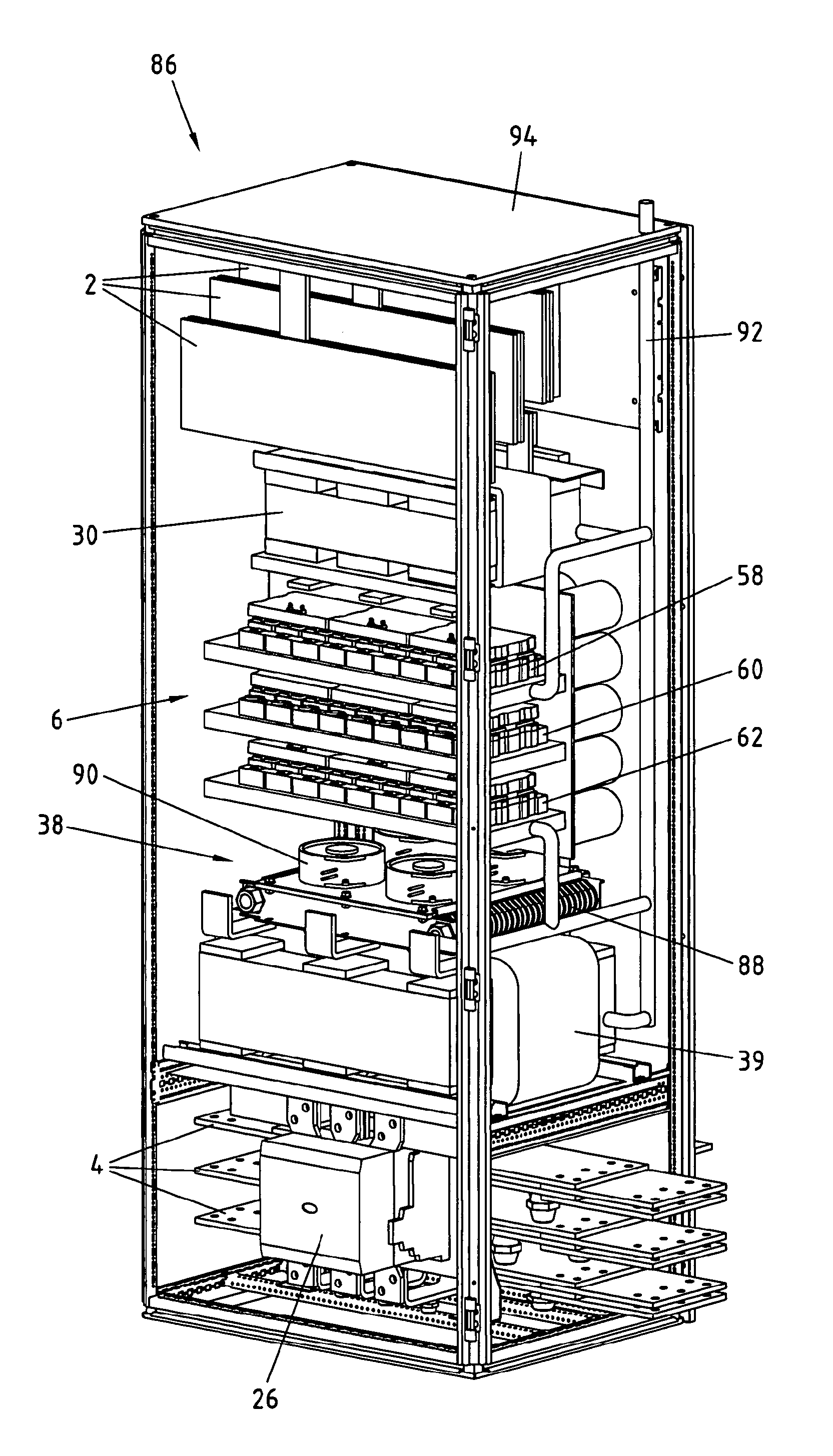
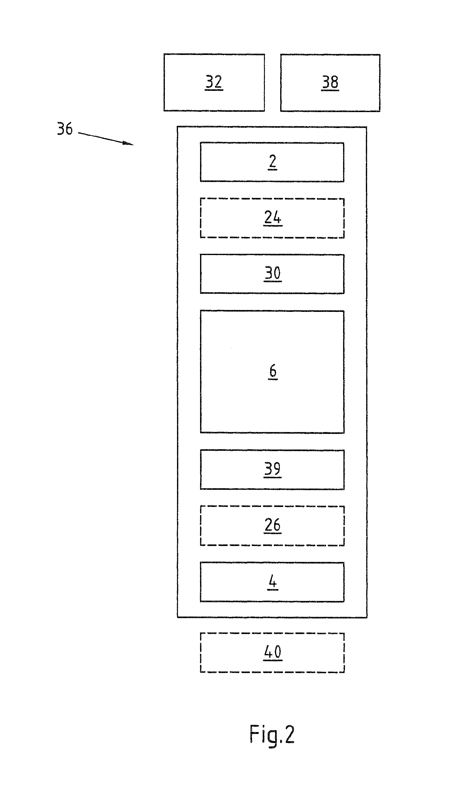
[0060]As can be seen from the circuit diagram, the power switch cabinet 1 comprises at a first end a machine connection 2 and at a second end a mains connection 4. In this exemplary embodiment both connections 2, 4 are formed with three conductors for providing three-phase current. These connections 2, 4 can be realised with cables or A.C. rails, preferably copper rails. A plurality of switch cabinets 1 can be connected in parallel via the machine connection 2 and electrically connected to a generator 68, for example a permanent-field synchronous machine. Via the mains connection 4 the power switch cabinet 1 is electrically connected to the mains, for example to a power supply network. Preferably the at least two power switch cabinets are connected in parallel via the mains connections 4. In this respect further components, such as switches or filters, in p...


PUM


Abstract

The invention relates to a switch cabinet arrangement of a device for generating electrical energy, wherein the switch cabinet arrangement comprises at least two separate power switch cabinets. The technical object of achieving an optimum scalability of devices for generating electrical energy with at the same time a simple installation and maintenance of the power switch cabinets despite a small available installation space, is achieved according to the invention in that the power switch cabinets respectively comprise a machine connection, a power module, a mains connection and a decentralised control unit, wherein the power module comprises a machine converter, a mains converter, a direct voltage intermediate circuit and a chopper, and wherein the power switch cabinets are electrically connected in parallel to one another via the machine connection and the mains connection.

Description

CROSS-REFERENCE TO RELATED PATENT APPLICATIONS[0001]This patent application is a continuation of pending PCT Application No. PCT / EP2012 / 056219, filed Apr. 4, 2012, which claims the benefit of German Application No. 102011001786.0, filed Apr. 4, 2011, the entire teachings and disclosure of which are incorporated herein by reference thereto.FIELD OF THE INVENTION[0002]The invention relates to a switch cabinet arrangement of a device for generating electrical energy, in which the switch cabinet arrangement comprises at least two separate power switch cabinets.BACKGROUND OF THE INVENTION[0003]It is known from the prior art to arrange electronic components, such as converters or filters, in particular of devices for generating electrical energy, in power switch cabinets. Wind turbines are often equipped with doubly-fed asynchronous machines, since in this way only partial outputs have to be transported via the converters of the equipment. However, with rotational speeds below the synchro...

Claims


Application Information

Patent Timeline
Patent Type & Authority Applications(United States)
IPC IPC(8): H02B1/32F03D9/00H02B1/56
CPCH02B1/32F03D9/002H02B1/565H02M7/003H02M7/493F03D9/25F03D9/257F03D80/82H02J2300/28H02J3/381Y02E10/76Y02E10/72H05K7/14325H05K7/1432H02B13/02
Inventor EICHLER, MARKUSNOWAK, HANS-GEORGHITPAMARIANNE
Owner CONVERTERTEC DEUT GMBH
Why Eureka
Try Eureka