Supercharge Your Innovation With Domain-Expert AI Agents!

Multidrum evaporator

a multi-drum evaporator and evaporator technology, applied in steam generation heating methods, steam generation using hot heat carriers, lighting and heating apparatus, etc., can solve the problems of prolonging the start-up time, prolonging the time required, and reducing the efficiency of evaporation

Active Publication Date: 2014-02-13
NOOTER ERIKSEN INC
View PDF1 Cites 7 Cited by
  • Summary
  • Abstract
  • Description
  • Claims
  • Application Information

AI Technical Summary

Benefits of technology

The patent text describes a new evaporator design for a heat recovery steam generator (HRSG) that is used in gas turbine power plants. The new design helps to improve the efficiency and speed of starting up the HRSG, while also reducing the amount of emissions during the start-up process. The new evaporator design uses a natural circulation-type evaporator with a large steam drum and thick walls to withstand high pressure. This design helps to protect the evaporator from damage and also allows for more efficient use of the HRSG in terms of its capacity and emissions requirements. Overall, the new design improves the performance and reliability of the HRSG in power plant applications.

Problems solved by technology

The extended start-up delays operating the HRSG at peak efficiency.
Moreover, the delay lengthens the time required to bring the HRSG—and any gas turbine with which it may be coupled—into compliance with emissions requirements.

Method used


Image

  • Multidrum evaporator
  • Multidrum evaporator
  • Multidrum evaporator

Examples


Embodiment Construction

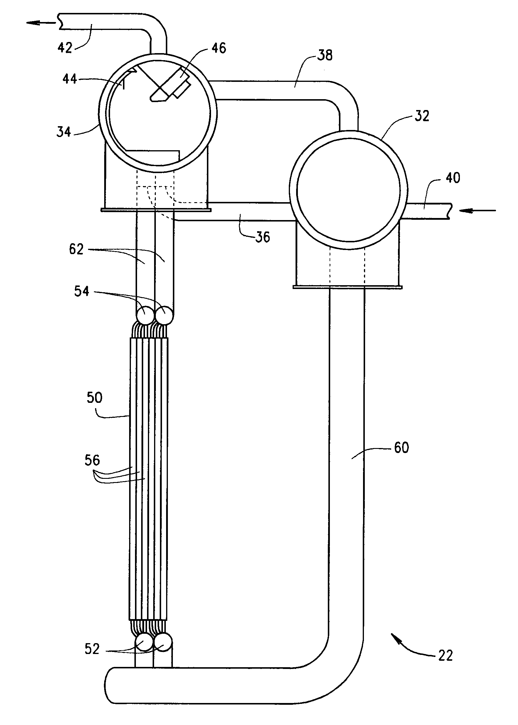
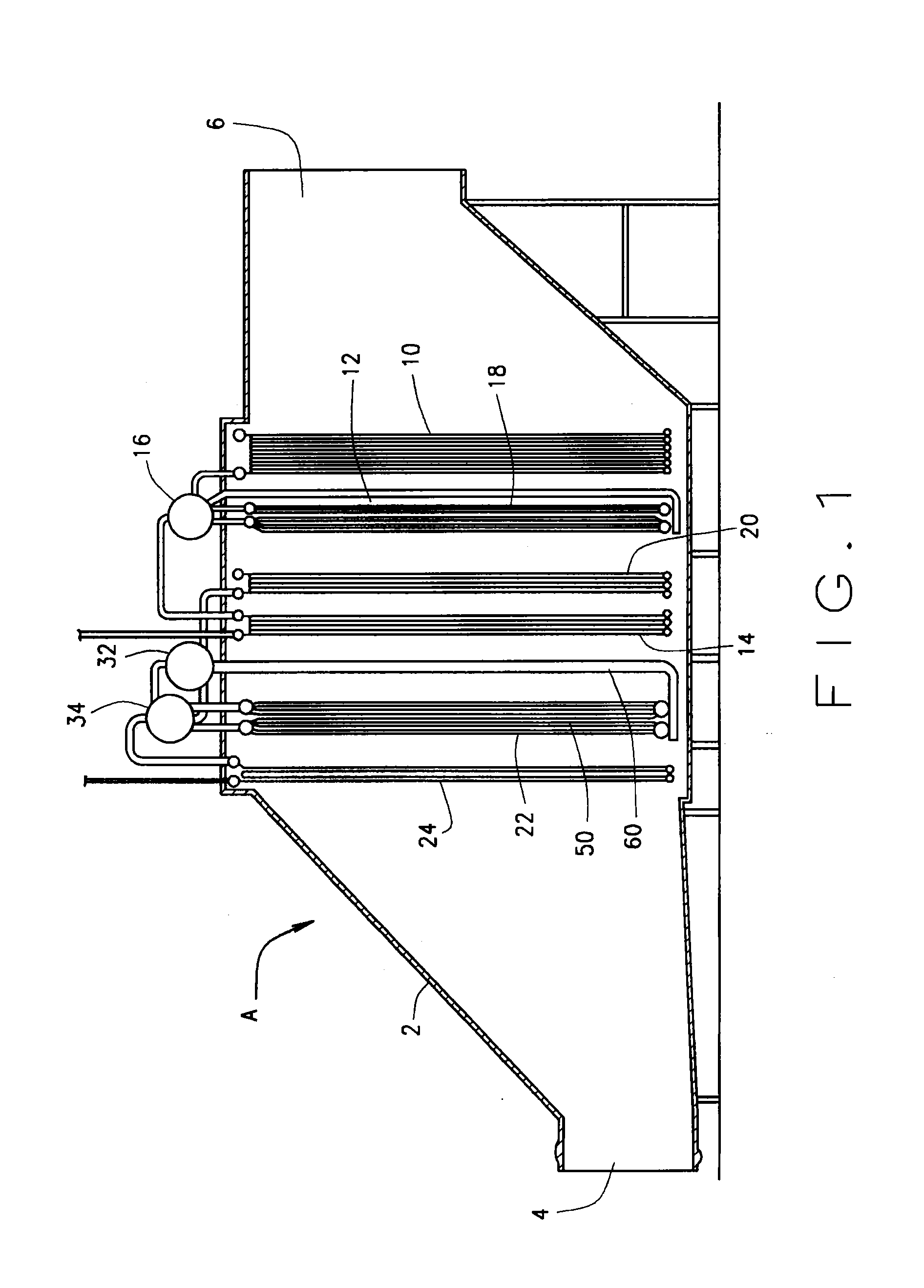
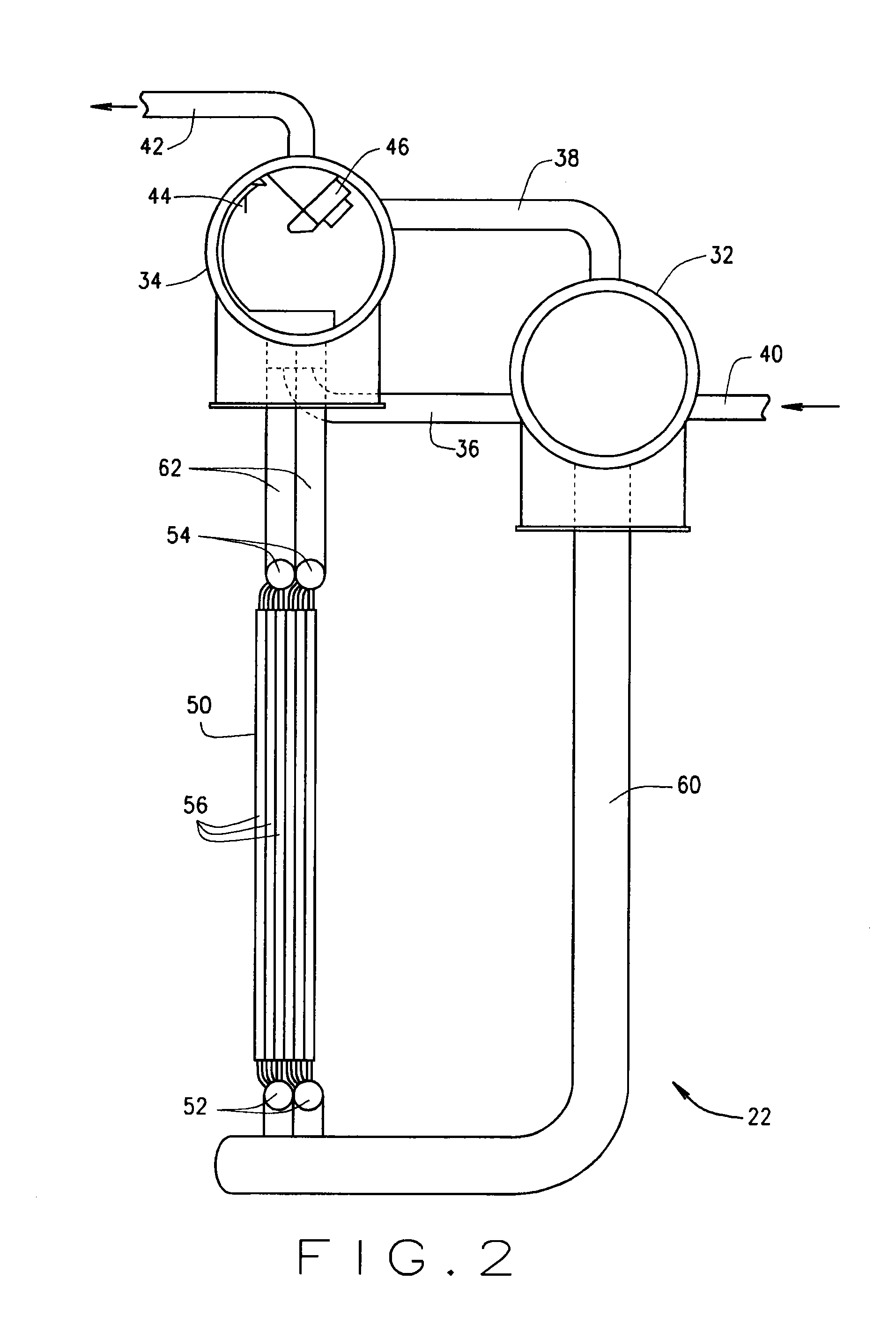
[0010]Referring now to the drawings, (FIG. 1), a heat recovery steam generator (HRSG) A has components, which are basically heat exchangers, organized in succession within a duct-like housing 2 for supplying superheated steam at low and high pressures. The housing 2 has an inlet 4 and an outlet 6. Hot gas, which may be the exhaust from a gas turbine, enters the housing 2 at the inlet 4 and within the housing 2 flows through the several components which extract heat from the gas and convert liquid feedwater into low and high pressure superheated steam.

[0011]Among the low pressure components of HRSG A are an economizer 10 for elevating the temperature of the feedwater, an evaporator 12 for converting the water from the economizer 10 into saturated steam, and a superheater 14 for converting the saturated steam from the evaporator 12 into superheated steam. The economizer 10, evaporator 12 and superheater 14 typically operate at a low pressure. The evaporator 12 may take the form of a c...


PUM


Abstract

An evaporator for a heat recovery steam generator has two horizontal steam drums of moderate size, one located slightly higher than the other. It also includes a coil having tubes located in the flow of a hot gas. The lower drum communicates with the inlets of the tubes for the coil. The outlets of the tubes communicate with the upper drum. A drain line connects the bottom of the upper drum with the lower region of the lower drum, so that water will flow from the upper drum to the lower drum. Water, which is primarily in the liquid phase, enters the lower drum through an inlet line and mixes with water from the upper drum. The mixture flows through into the coil. Here some of it transforms into saturated steam while the rest remains as saturated water. The saturated steam and saturated water flow into the upper drum where the steam escapes and the water flows back into the lower drum to recirculate through the coil. Owing to their moderate sizes, the drums can withstand high pressures without having excessive wall thickness, and this enables the evaporator to be set into operation with minimal or no hold points. Yet the two drums provide a retention time—and the protection that it provides—of a single large capacity drum having substantial wall thickness.

Description

RELATED APPLICATION[0001]This application derives priority from and otherwise claims the benefit of U.S. provisional patent application 61 / 478695 filed 25 Apr. 2011, which is incorporated herein by reference.TECHNICAL FIELD[0002]This invention relates in general to the transformation of liquid water into saturated steam and more particularly to an evaporator for producing saturated steam and to a process utilized by the evaporator.BACKGROUND ART[0003]The gas turbines that power electrical generators discharge exhaust gases at extremely high temperatures. Heat recovery steam generators (HRSGs) extract the heat from the gases to produce steam that powers steam turbines that in turn drive more electrical generators.[0004]The typical HRSG includes multiple heat exchangers located one after the other in the flow of a hot exhaust gas from a gas turbine. Among heat exchangers are an economizer for elevating the temperature of feed water, an evaporator for converting the higher temperature ...

Claims


Application Information

Patent Timeline
Patent Type & Authority Applications(United States)
IPC IPC(8): F28D15/00
CPCF28D15/00F22B21/18Y02E20/16F22B1/18F22B1/1815F22D1/04
Inventor JACKSON, BRADLEY N.
Owner NOOTER ERIKSEN INC
Features
  • R&D
  • Intellectual Property
  • Life Sciences
  • Materials
  • Tech Scout
  • Unparalleled Data Quality
  • Higher Quality Content
  • 60% Fewer Hallucinations
Learn More