
Enhanced oil recovery initiated with zero emission in-situ combustion

a technology of in-situ combustion and petroleum fluid, which is applied in the direction of fluid removal, earthwork drilling and mining, and well accessories, etc. it can solve the problems of high oxygen concentration, fire and/or explosion, and well destruction, and achieves enhanced recovery of petroleum fluids, high oil displacement efficiency, and promote gravity segregation

Inactive Publication Date: 2014-02-13
BELGRAVE JOHN
View PDF4 Cites 16 Cited by
  • Summary
  • Abstract
  • Description
  • Claims
  • Application Information

AI Technical Summary

Benefits of technology

The present invention provides an enhanced oil recovery method through in-situ combustion in high relief formations. The method involves injecting an oxidizing gas into the formation through an injection well and initiating an in-situ combustion operation. The flue gas generated by the combustion is recycled back into the formation to promote gravity segregation between the gas and oil phases, high oil displacement efficiency, lower temperature, and reduced oxygen concentration levels. The method also involves controlling the production rate of flue gas to promote safety and prevent explosions. The invention can achieve improved oil recovery from high relief formations while reducing the risk of fires or explosions. The method utilizes the recycling of flue gas to pressurize the formation and reduce the possibility of channeling the flue gas to any one production well. The amount of oxidizing gas in the gas mixture injected into the formation is gradually reduced.

Problems solved by technology

While carbon dioxide flooding enhances oil recovery, economic considerations restrict the process to locations where a source of carbon dioxide is readily available.
Although there are many advantages to in-situ combustion over other methods of enhanced oil recovery, there are several drawbacks including, the risk of high temperature propagation towards production wells causing the destruction of the well and the risk of gas high in oxygen concentration reaching the producing wells which can result in fire and / or explosion.

Method used


Image

  • Enhanced oil recovery initiated with zero emission in-situ combustion
  • Enhanced oil recovery initiated with zero emission in-situ combustion
  • Enhanced oil recovery initiated with zero emission in-situ combustion

Examples


Embodiment Construction

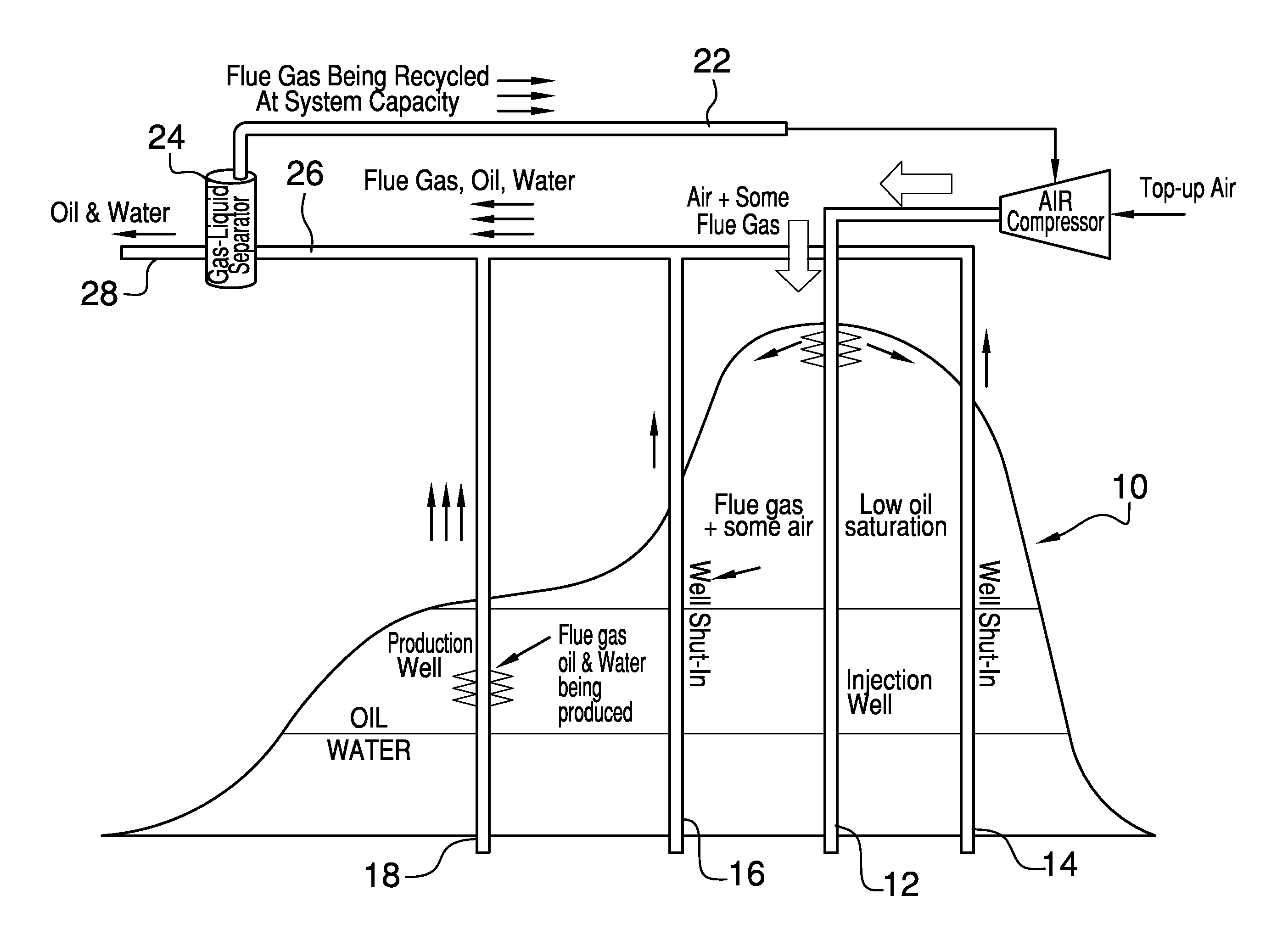
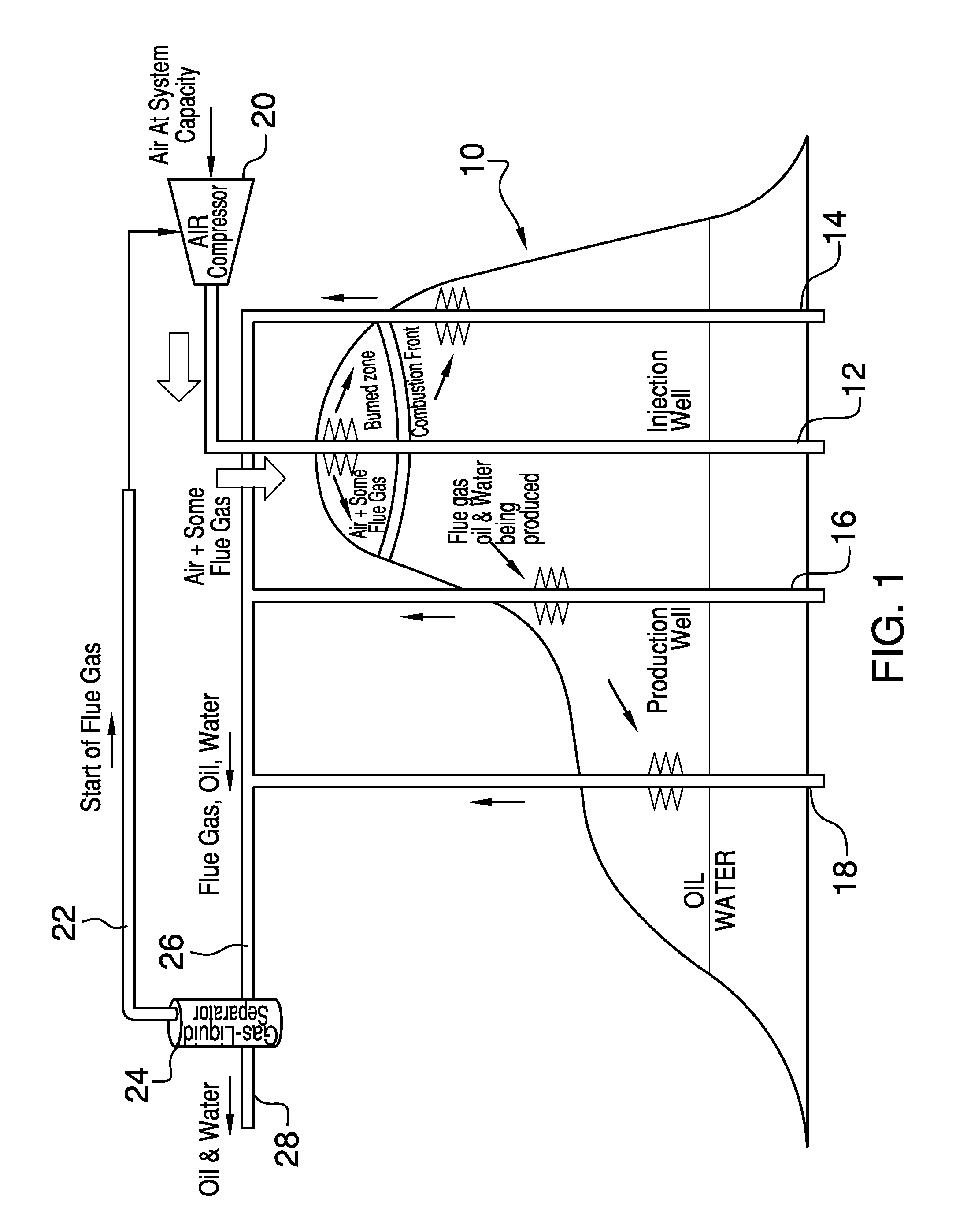
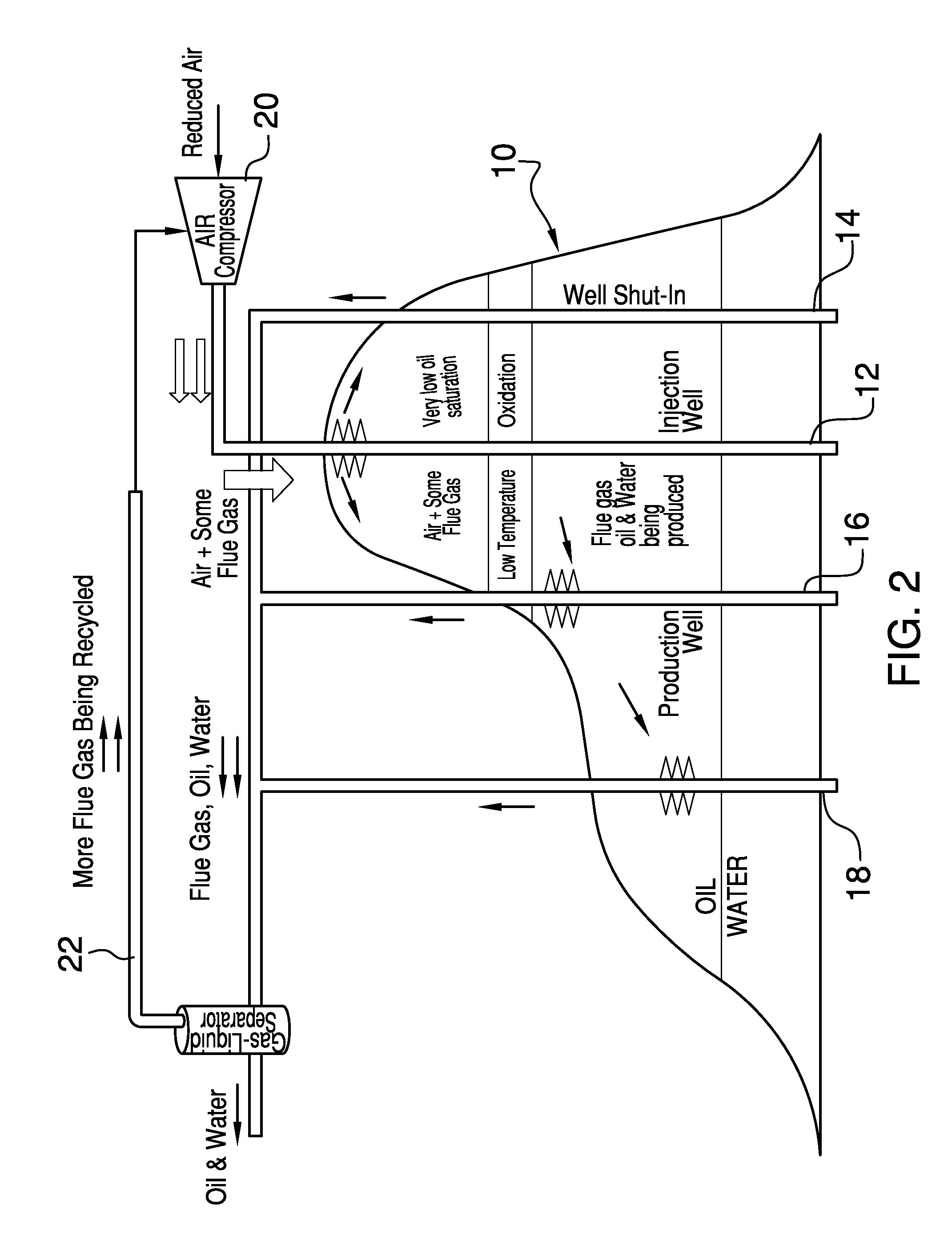
[0027]Several embodiments of the present invention are described below and illustrated in the accompanying drawings. In embodiments, there is an in-situ combustion method for the enhanced recovery of petroleum fluids from vertical or high relief subterranean formations or reservoirs where gravity segregation of flue gas and oil is utilized to provide increased sweep efficiency by controlling the rate in which flue gas is produced and by recycling recovered flue gas back into the well to establish and maintain well pressure, while reducing and ultimately eliminating oxidizing gas injection. Although the oxidizing gas may be any gas or mixture of gases that support combustion, in an embodiment, the oxidizing gas is atmospheric air. Advantages of using atmospheric air include being readily available at the well site and not requiring specialized equipment to provide a suitable supply for formation injection.

[0028]All of the flue gas produced from the formation is separated from formati...


PUM


Abstract

The invention provides an enhanced oil recovery process that may be used in light oil reservoirs, and which is particularly beneficial in high-relief formations. The process includes an initial injection of air into the formation through an injection well to support the in-situ combustion and mobilize formation fluids. Produced flue gas is recovered and recycled into the formation by injection through an injection well. Initially, gas production is restricted for the purpose of increasing the gas injection to recovery ratio to pressurize the formation. With an increase in formation pressure, the rate of air injection is gradually reduced as the rate of recovered flue gas injection increases. Combustion front propagation in the formation is controlled by the rate of production at each actively producing well to ensure good horizontal sweep across the well and to prevent channeling to one or more production wells.

Description

FIELD OF THE INVENTION[0001]The present invention relates generally to the enhanced recovery of petroleum fluid from subterranean formations by in-situ combustion. More particularly, the present invention relates to an in-situ combustion method for the enhanced recovery of petroleum fluids that results in increased recovery efficiency and reduced environmental impact by controlling the gas production rate across each producing well and by recycling recovered combustion gas that is rich in carbon dioxide back into the formation.BACKGROUND OF THE INVENTION[0002]Various enhanced oil recovery processes are used to improve recovery of oil and other formation fluids from subterranean formations. Enhanced oil recovery processes include chemical injection, gas injection, and thermal recovery. The focus herein is primarily made in reference to gas injection and thermal recovery processes.[0003]Gas injection involves the forced injection of various gas mixtures into the subterranean formation...

Claims


Application Information

Patent Timeline
IPC IPC(8): E21B43/24
CPCE21B43/164E21B43/243
Inventor BELGRAVE, JOHN
Owner BELGRAVE JOHN
Learn More