In-situ calibration system and method for radiation monitors

a radiation monitor and in-situ calibration technology, which is applied in the direction of calibration apparatus, optical radiation measurement, instruments, etc., can solve the problems of increasing the risk of accidents, increasing the cost of facility operators, and inconvenience and annoyance of nuclear facility institutions

Inactive Publication Date: 2014-02-13
INST NUCLEAR ENERGY RES ROCAEC
View PDF8 Cites 25 Cited by
  • Summary
  • Abstract
  • Description
  • Claims
  • Application Information

AI Technical Summary

Benefits of technology

[0007]Another embodiment of the present invention provides an in-situ calibration method for radiation monitors, comprising steps of: providing a portable irradiator, a laser locator, a working standard part, an irradiator lifter, a laser range finder, a monitor to be calibrated and a portable surveymeter of a site background; setting performance evaluations of the portable irradiator, comprising the effect field, beam uniform, and back scattering; setting performance evaluations of the working standard part, comprising the accuracy, stability, response time, ener

Problems solved by technology

However, fixed outdoor type nuclear facility environmental monitors and indoor type nuclear facility control area monitors require continuous monitoring; therefore, when calibration is required, facility operators need to prepare at least one standby instrument to replace an instrument to be delivered for calibration, which virtual

Method used


Image

  • In-situ calibration system and method for radiation monitors
  • In-situ calibration system and method for radiation monitors
  • In-situ calibration system and method for radiation monitors

Examples


Embodiment Construction

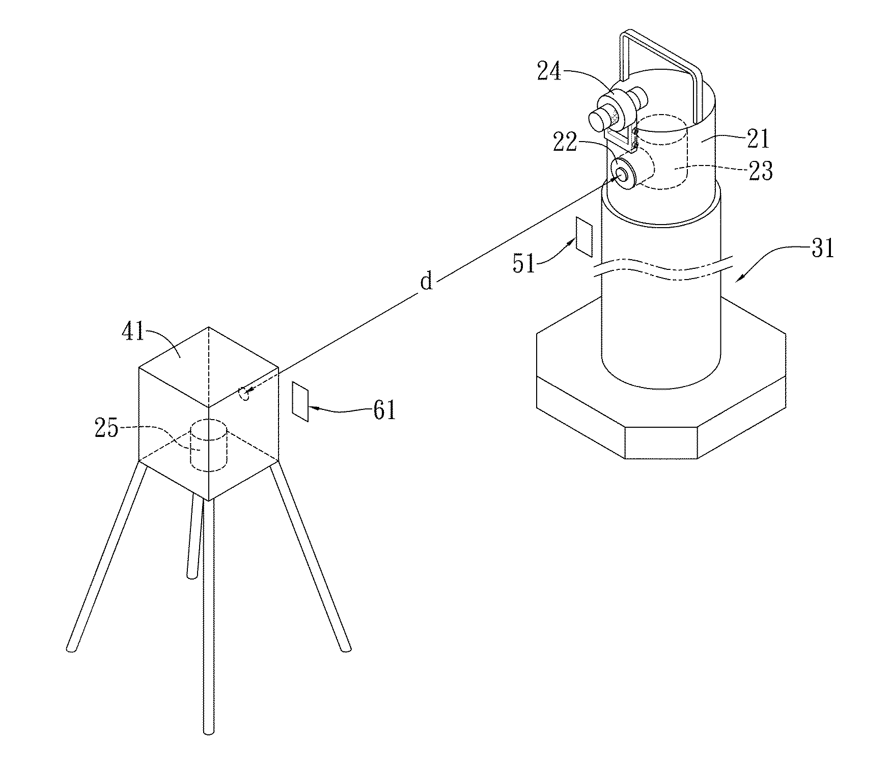
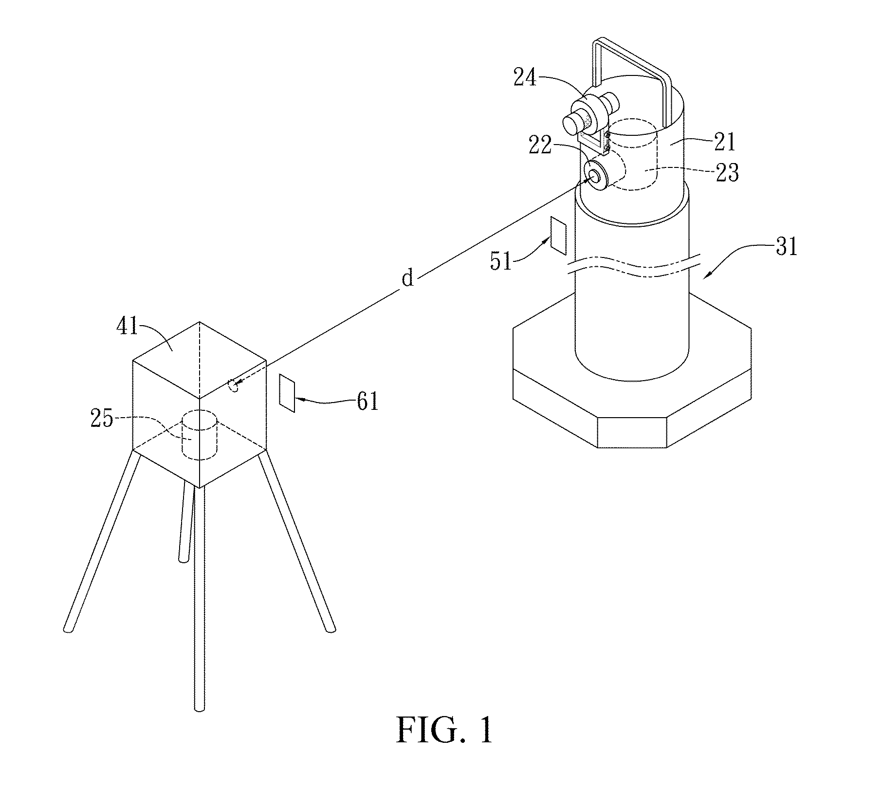
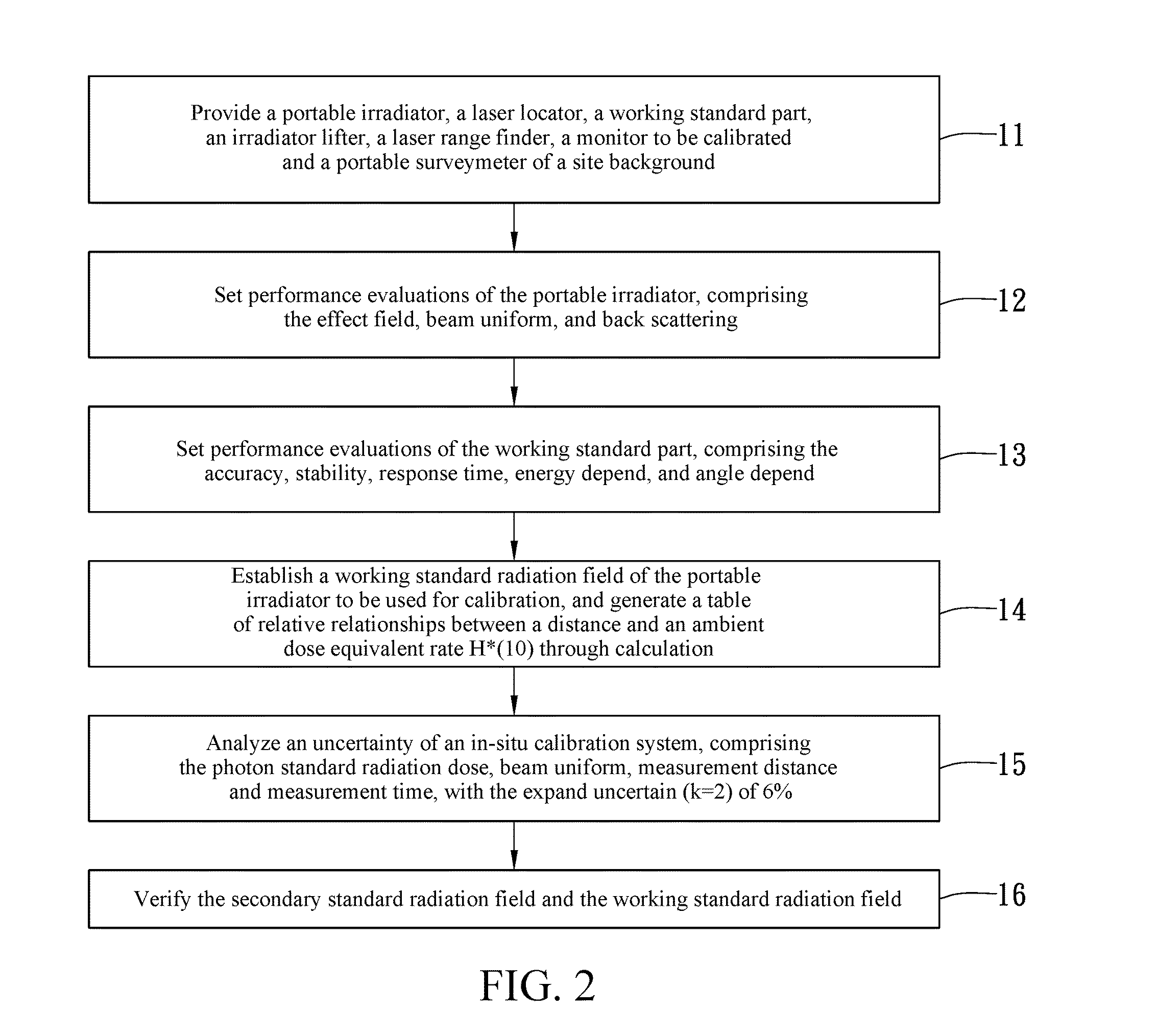
[0015]The present invention uses a spherical ionization chamber that dates back to an air kerma-rate primary standard to establish a secondary standard radiation field, uses a scintillation surveymeter with good calibration performance evaluations in the secondary standard radiation field, and a working standard part obtaining the ambient dose equivalent rate, in cooperation with a portable irradiator and an irradiator lifter and a laser range finder of a relevant radiation source, and is capable of directly performing in-situ calibration on fixed, or large-scale, or continuous monitoring-type radiation monitors to be calibrated that are stationed in nuclear power plants, nuclear medical departments, and other nuclear facility operating institutions; results of a calibration dose rate indicate that the accuracy conforms to requirements of the American National Standards Institute (American National Standards Institute, ANSI) N323A specifications.

[0016]An embodiment of the present in...


PUM


Abstract

By using a scintillation surveymeter with good calibration performance evaluation for a secondary standard radiation field, and a working standard part obtaining an ambient dose equivalent rate, in cooperation with a portable irradiator, and an irradiator lifter, a laser range finder and a laser locator of a relevant radiation source, in-situ calibration is capable of being performed on fixed, or large-scale, or continuous monitoring type radiation monitors to be calibrated stationed in nuclear power plants, nuclear medical departments, and other nuclear facility operating institutions. Moreover, a time-efficient and effective in-situ calibration method is further provided, which can be performed based upon a standard calibration field that is achieved using a portable 137Cs radiation source. The in-situ calibration method is capable of saving the trouble of delivering large-scale monitors, or monitors difficult to move, or monitors requiring continuous monitoring to calibration laboratories for scheduled calibration.

Description

BACKGROUND OF THE INVENTION[0001]1. Field of Invention[0002]The present invention relates to an in-situ calibration system and method for radiation monitors, and in particular, to a calibration system and method for ambient dose monitors and area monitors provided with an in-situ calibration mode.[0003]2. Related Art[0004]It is well-known that, radiation monitors need to be delivered to qualified laboratories for calibration. However, fixed outdoor type nuclear facility environmental monitors and indoor type nuclear facility control area monitors require continuous monitoring; therefore, when calibration is required, facility operators need to prepare at least one standby instrument to replace an instrument to be delivered for calibration, which virtually increases costs of the facility operators. In addition, monitors are delivered back and forth between workplaces and calibration laboratories, which is time-consuming and increases a risk of accidents. As a result, the aforesaid me...

Claims


Application Information

Patent Timeline
IPC IPC(8): G01T1/16G01T1/20
CPCG01T1/02G01T7/00G01T7/005H01J49/0009
Inventor YEH, CHIN-HSIENYUAN, MING-CHEN
Owner INST NUCLEAR ENERGY RES ROCAEC
Why Eureka
Try Eureka