Remote Rotor Parameter Sensor for Electric Drives

a technology of parameter sensor and electric drive, which is applied in the direction of electric device, electric converter control, dynamo-electric converter, etc., can solve the problems of demagnetization of magnets, no particular diagnostic system for the rotor of electric engine or motor, etc., to prolong the operating range or lifetime of the rotor and/or the electric engine, improve engine performance, and boost performance

Active Publication Date: 2014-02-13
INFINEON TECH AG
View PDF25 Cites 25 Cited by
  • Summary
  • Abstract
  • Description
  • Claims
  • Application Information

AI Technical Summary

Benefits of technology

[0018]Using a diagnostic system with sensor measurement according to the present invention makes it possible to extend the operating range or lifetime of the rotor and / or the electric engine by avoiding critical operation situations, critical temperatures or briefly boosting the performance. For induction motors, the present invention provides the possibility for efficiency optimization, as the rotor resistance may be better estimated via the measured rotor temperature, whereby the engine performance can be improved as a whole.
[0019]According to another embodiment of the present invention, one or more preferably wireless sensors are arranged at the rotor of the electric engine for sensing temperature, acceleration and / or the magnetic field in the rotor. As there may occur strong magnetic fields in the rotor, it is possible to obtain the power supply for the sensors via energy harvesting from the motion of the rotor. This can be achieved, via inductive energy generation or harvesting electric energy from the motion of the rotor. The wireless transmission system of the present invention requires less or no maintenance and can easy be integrated in the electrical motor.

Problems solved by technology

Such engines are safety-critical, since they directly affect the driving of the vehicle.
Yet, there does not exist any particular diagnostic system for the rotor of an electric engine or motor.
The rotor of an electric engine or motor may encounter various errors or failure situations, for example, fracture of the bars in an asynchronous induction motor or additional power losses in the metal components, which may result in a demagnetization of magnets within magnetic-flux creating components and / or magnetic-flux leading components of the motor.

Method used


Image

  • Remote Rotor Parameter Sensor for Electric Drives
  • Remote Rotor Parameter Sensor for Electric Drives

Examples


Embodiment Construction

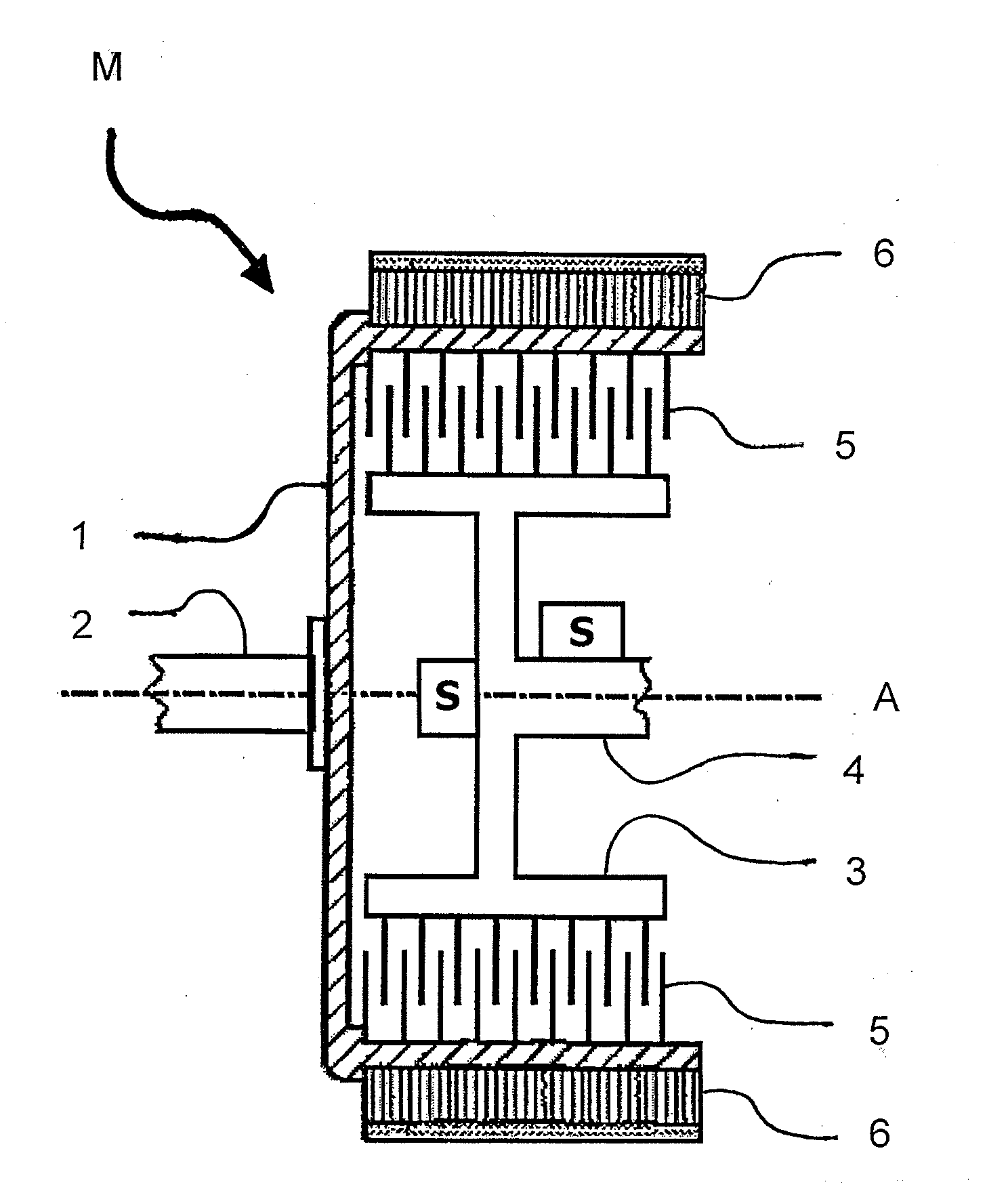
[0028]The parts of the electric motor shown in The FIGURE comprise a stator 1 that is supported via a bearing or shaft 2. Depending on the kind of electric engine or motor the stator may be fixed or supported such that it may rotate around the shaft 2. The stator part encompasses, at least in part, a rotor 3 that is supported via a bearing or shaft 4 such that the rotor 3 can rotate in the stator 1.

[0029]The stator 1 is substantially shaped like an open cylinder with an outer and an inner circumferential surface substantially axis symmetrical with respect to a center or rotation axis A shown as dotted line. One or more electromagnetic field producing components or coils 6 are arranged at the outer circumferential cylinder surface of the stator 1.

[0030]The electromagnetic field producing components or coils 6 are arranged and adapted, when under electric power, to produce an electromagnetic field that inductively influences the rotor 3 inside of the stator 1. Thus, the stator 3 funct...


PUM


Abstract

A rotor parameter sensor can be used for electric drives. A rotor of an electric engine or motor is monitored by a sensor sensing one or more physical observables or operation parameters. Furthermore, a method and system can be used for monitoring an electric engine or motor for use in electric or hybrid vehicles.

Description

TECHNICAL FIELD[0001]The present invention relates to a rotor of an electric drive, an electric engine or engine and a vehicle drive apparatus for an electric driven vehicle or an electric driven train. In particular, the invention relates to a remote rotor parameter sensor for electric drives.BACKGROUND[0002]As vehicles improved in fuel economy, fuel cell vehicles and hybrid vehicles have been of great interest. The hybrid vehicle includes as its component a gasoline engine, a transmission, an inverter, a battery, a motor as well as their controllers. Such vehicles require a motor that is highly reliable, efficient, variable in rpm and superior in control.[0003]Environmental requirements like reduction of carbon dioxide emissions require improvement in fuel economy and enhancement of electric machines for driven vehicles of all kinds. Electrical machinery and its use as power source or additional power source in a motor vehicle for electric or hybrid vehicles are commonly known.[00...

Claims


Application Information

Patent Timeline
Patent Type & Authority Applications(United States)
IPC IPC(8): H02K11/00
CPCB60L2220/44H02K11/20H02K11/35Y02T10/64H02K11/21H02K11/25H02P8/34
Inventor BROCKERHOFF, PHILIP GEORGWELPONER, MATTIAS
Owner INFINEON TECH AG
Why Eureka
Try Eureka