Service Instance Mapping Method, Apparatus and System

a mapping method and service instance technology, applied in the field of communication technologies, can solve the problems of hardly planning properly beforehand, unable to support more tenant services on a network device, and the use rate of a valid path of an entire network by the network, so as to achieve a higher service development capability and support the capability of service labels

Active Publication Date: 2014-02-13
HUAWEI TECH CO LTD
View PDF6 Cites 43 Cited by
  • Summary
  • Abstract
  • Description
  • Claims
  • Application Information

AI Technical Summary

Benefits of technology

[0017]In the service instance mapping method, apparatus, and system in the embodiments of the present invention, after a layer-2 service instance is correlated with a service access port of the service instance, a service instance identifier corresponding to the service access port may be mapped to a service label of a packet. Because the service label is adopted to carry the service instance identifier, a higher service label supporting capability may be included, more service instances may be supported, and a multi-tenant requirement in a large-scale public cloud environment can be met; control protocol support is extended, and extension of the TRILL protocol can fulfill a higher service development capability.

Problems solved by technology

A traditional L2 technology cannot support multiple network paths, the utilization rate of a valid path of an entire network by the network after breaking loops by using a technology related to the Spanning Tree Protocol (STP for short) is very low, and a greater server cluster and a wider virtual machine migration range need a larger L2 network.
In construction of the public cloud, a huge number of service instances are required for identifying multiple tenants, and how to support more tenant services on a network device is also a problem.
Compared with the TRILL protocol, the fixed routing manner of the SPB protocol cannot ensure maximum traffic load balance, the data center itself has much uncertain bursty traffic, and mapping can hardly be planned properly beforehand without a clear traffic model.
Therefore, the SPB protocol is more vulnerable to a congested hotspot.
In summary, although the hop-by-hop ECMP balancing manner of the TRILL protocol is obviously better, but the number of service instances is small and cannot satisfy more than 4K service instances.
For example, it cannot meet a multi-tenant requirement from a public cloud.

Method used


Image

  • Service Instance Mapping Method, Apparatus and System
  • Service Instance Mapping Method, Apparatus and System
  • Service Instance Mapping Method, Apparatus and System

Examples


embodiment 1

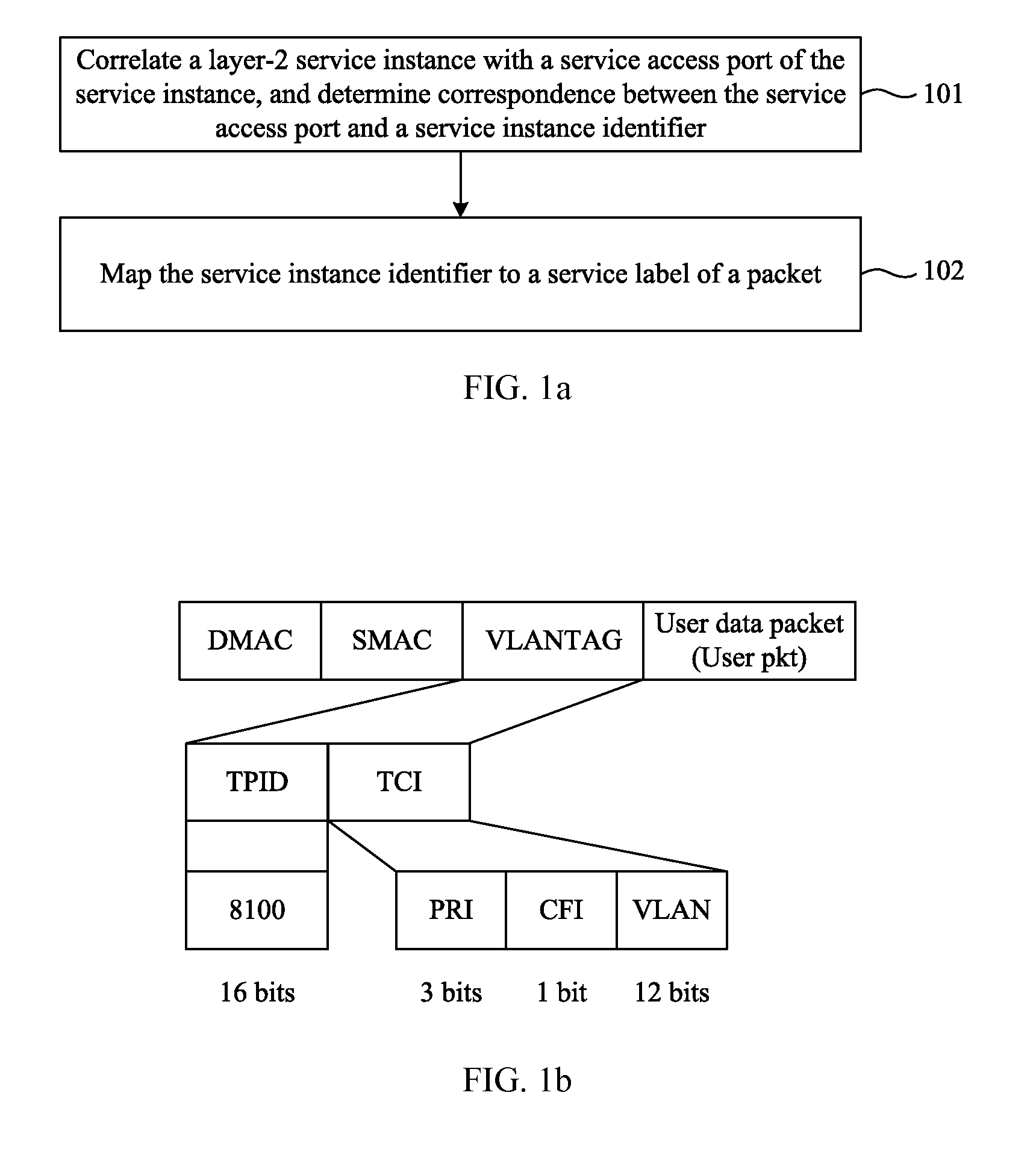
[0029]FIG. 1a is a flowchart of a service instance mapping method according to Embodiment 1 of the present invention. As shown in FIG. 1a, the service instance mapping method may specifically include:

[0030]Step 101: Correlate a layer-2 service instance with a service access port of the service instance, and determine correspondence between the service access port and a service instance identifier.

[0031]The service instance in the embodiment of the present invention is a layer-2 (data link layer) network service. Different service instances are isolated in a network by means of layer-2 isolation, and correlation between the service access port of the service instance and the service instance may be specified in a command configuration manner. For example:

[0032][RB1] service instance 100 name “S1” / / create a service instance S1;

[0033][PE2] interface vlanif 10

[0034][PE1-Vlanif10]12 binding service instance S1 / / correlate the service instance S1 with a vlan service access port interface...

example 1

[0062]The virtual local area network identifier of the service instance is mapped to a virtual local area network field of a second virtual local area network tag in the Transparent Interconnection of Lots of Links packet.

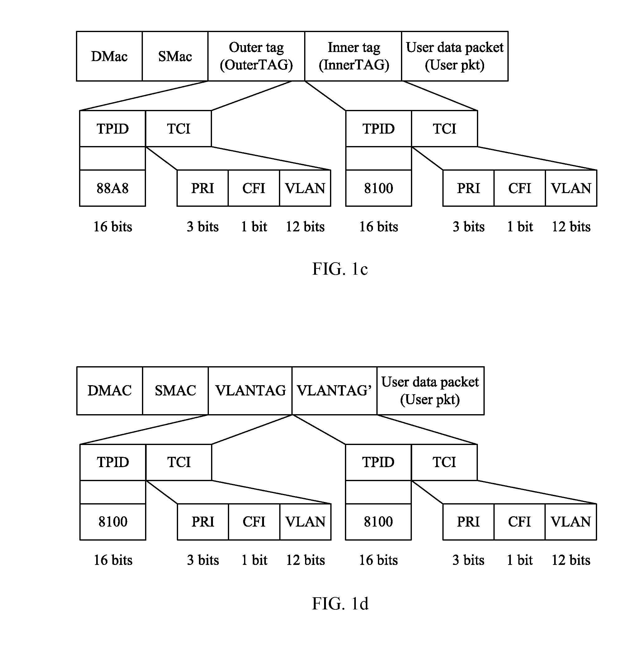
[0063]FIG. 1d is another schematic diagram of an 802.1q encapsulation format adopted in a TRILL packet in the service instance mapping method according to Embodiment 1 of the present invention. As shown in FIG. 1d, the first virtual local area network tag in the Transparent Interconnection of Lots of Links (TRILL) packet mentioned in the foregoing example may be a VLANTAG (reference may also be made to FIG. 1b), and the second virtual local area network tag in the TRILL packet may be a newly added VLANTAG′; certainly, it is also feasible that the first virtual local area network tag is a VLANTAG′ and the second virtual local area network tag is a VLANTAG. In this way, the TRILL packet not only can carry the service instance identifier in the first virtual local are...

example 2

[0064]The virtual local area network identifier of the service instance is mapped to a virtual local area network field of a second outer tag and / or a virtual local area network field of a second inner tag in a dual-layer virtual local area network stacking packet.

[0065]Similar to example 1, on the basis of FIG. 1c, an OuterTAG′ and an InnerTAG′ may be newly added. If the first outer tag of the dual-layer virtual local area network stacking (QinQ) packet is an OuterTAG, the second outer tag is an OuterTAG′; if the first inner tag is an InnerTAG, the second inner tag is an InnerTAG′, and vice versa. The original VLAN identifier of the service instance is carried in the second outer tag and / or the second inner tag. Both the service label and the VLAN identifier may be carried, so as to be compatible with the original TRILL protocol.

[0066]In a TRILL network, a layer-2 service instance is identified by adopting an extended service label, and a more flexible service mapping manner is req...


PUM


Abstract

The present invention discloses a service instance mapping method, apparatus and system. The service instance mapping method includes: correlating a layer-2 service instance with a service access port of the service instance, and determining correspondence between the service access port and a service instance identifier; and mapping the service instance identifier to a service label of a packet. In embodiments of the present invention, because the service label is adopted to carry the service instance identifier, a higher service label supporting capability may be included, more service instances may be supported, and a multi-tenant requirement in a large-scale public cloud environment can be met; control protocol support is extended, and extension of a TRILL protocol can fulfill a higher service development capability.

Description

[0001]This application is a continuation of International Application No. PCT / CN2011 / 073322, filed on Apr. 26, 2011, which is hereby incorporated by reference in its entirety.TECHNICAL FIELD[0002]Embodiments of the present invention relate to the field of communications technologies, and in particular, to a service instance mapping method, apparatus and system.BACKGROUND[0003]Under the support of virtualization technologies, cloud computing can provide a scalable resource pool of computing, storage, and application services. A main development trend of cloud computing is to construct a network architecture having a high-capacity non-blocking data center, and various types of service applications can be supported on this basis. A network device needs to support a larger server cluster, migrate a virtual machine in a wider range when the virtual machine is applied, and ensure service continuity in a migration process. Therefore, cloud computing needs to meet the following three networ...

Claims


Application Information

Patent Timeline
Patent Type & Authority Applications(United States)
IPC IPC(8): H04L12/801H04L12/723H04L45/50
CPCH04L45/50H04L47/17H04L12/4662
Inventor LI, FEILI, YIZHOU
Owner HUAWEI TECH CO LTD
Why Eureka
Try Eureka