Blade for a continuous-flow machine and a continuous-flow machine

a continuous-flow machine and continuous-flow technology, which is applied in the direction of liquid fuel engines, marine propulsion, vessel construction, etc., can solve the problems of leaving quite a bit of room for improvement, and achieve the effects of reducing maintenance costs, reducing maintenance costs, and reducing maintenance costs

Active Publication Date: 2014-02-13
MTU AERO ENGINES GMBH
View PDF5 Cites 7 Cited by
  • Summary
  • Abstract
  • Description
  • Claims
  • Application Information

AI Technical Summary

Benefits of technology

[0018]A preferred continuous-flow machine has at least one row of blades that is made up of the blades according to the invention. In particular, the blades are runner blades. Such a row of blades has blades whose vibrational stresses are reduced in the tip section as compared to conventional blades with tapered blade tips. As a result, the blades can withstand greater stress than the conventional blades, so that their service life can be increased and the efficiency of the continuous-flow machine can be improved.

Problems solved by technology

These prior-art configurations of the blade tips translate into a reduction of the vibrational stresses in the area of the blade tip, but they still leave quite a bit of room for improvement.

Method used


Image

  • Blade for a continuous-flow machine and a continuous-flow machine
  • Blade for a continuous-flow machine and a continuous-flow machine
  • Blade for a continuous-flow machine and a continuous-flow machine

Examples


Embodiment Construction

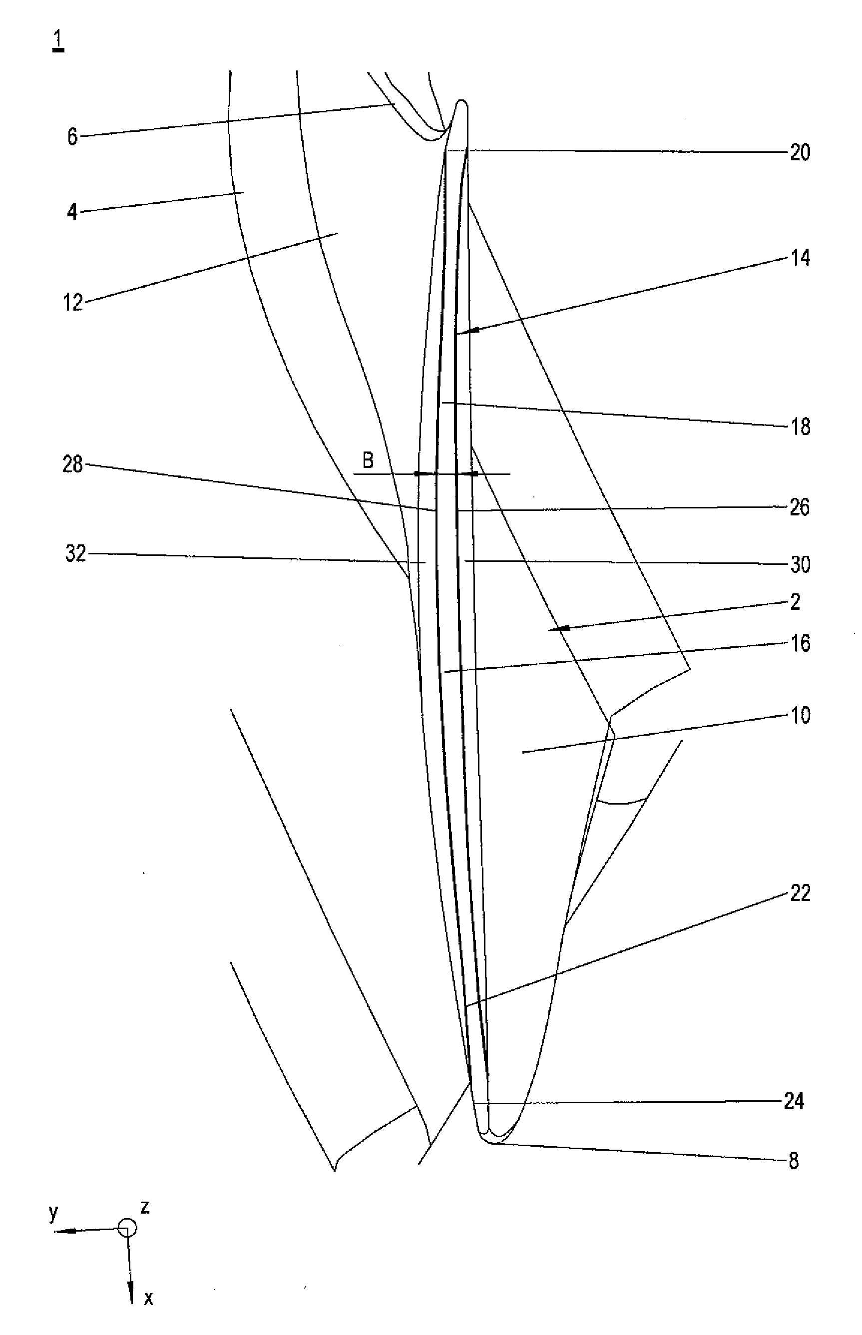
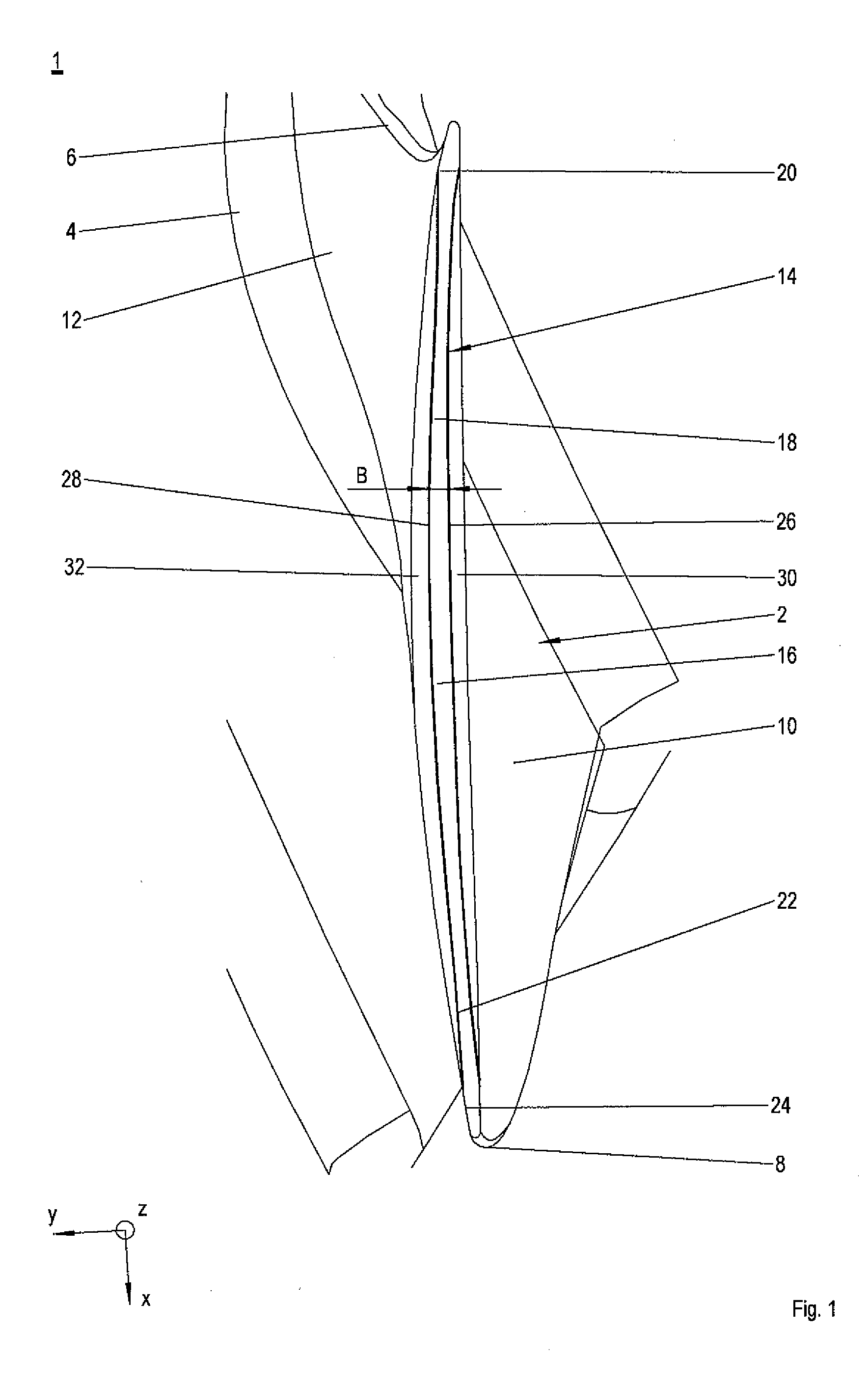
[0026]FIG. 1 shows a top view of a runner blade 1 of a continuous-flow machine in the main direction z. The runner blade 1 can be arranged on the turbine side as well as on the compressor side. For example, the runner blade 1 having identical blades forms a row of runner blades of a high-pressure compressor. The continuous-flow machine is preferably an axial continuous-flow machine and especially an aircraft engine.

[0027]The runner blade 1 has a blade 2 that extends from a platform 4 in the main direction z of the runner blade 1. The blade 2 has a leading edge 6 and a trailing edge 8 opposite from it which run in the main direction z and are at a distance from each other in the lengthwise direction x of the runner blade 1. A pressure-side wall 10 as well as a suction-side wall 12 opposite from the pressure-side wall 10 extend between the leading edge 6 and the trailing edge 8. The pressure-side wall 10 and the suction-side wall 12 form a blade profile and are delimited in the main d...


PUM


Abstract

A blade for a continuous-flow machine is disclosed, especially an aircraft engine, whereby, starting from the middle section, the cross section of the blade tip is reduced with respect to the middle section, at least over a front partial section in the direction of the leading edge and over at least a rear section in the direction of the trailing edge, and a continuous-flow machine having at least one row of blades including such blades is also disclosed.

Description

[0001]This claims the benefit of European Patent Application EP 12179769.0, filed Aug. 9, 2012 and hereby incorporated by reference herein.[0002]The invention relates to a blade for a continuous-flow machine, and it also relates to a continuous-flow machine.BACKGROUND[0003]The tips of blades in continuous-flow machines, for example, of runner blades in aircraft engines, are regularly exposed to vibrational stresses. The vibrational stresses can manifest themselves, for example, in the form of cracks either in the armoring on the tip side and / or in the blade body. In order to reduce vibrational stresses in the blade tips, it has been long known to configure the blade tips with a tapered cross section with respect to adjacent blade sections. Such blade tips, also referred to as “squealer tips”, are known in many variations and can be configured on both sides, that is to say, on the pressure side as well as on the suction side, or else only on one side, that is to say, for example, onl...

Claims


Application Information

Patent Timeline
Patent Type & Authority Applications(United States)
IPC IPC(8): F01D5/14
CPCF01D5/141F01D5/20F04D29/164F04D29/681F04D29/324Y02T50/60
Inventor GEPPERT, JOHANNEIBELSHAEUSER, PETERRAUSCHMAIR, HEINZ
Owner MTU AERO ENGINES GMBH
Why Eureka
Try Eureka