Vessel comprising a mooring connector with a heave compensator

a technology of heave compensation and mooring connector, which is applied in the field of vessels, can solve the problems of reducing the heat generation of lifting wires during heave compensation, and achieve the effect of reducing power and reducing lifting for

Active Publication Date: 2014-02-13
SINGLE BUOY MOORINGS INC
View PDF1 Cites 6 Cited by
  • Summary
  • Abstract
  • Description
  • Claims
  • Application Information

AI Technical Summary

Benefits of technology

[0013]In a preferred embodiment of a vessel according to the invention, a connector is attached to the free end of the arm for engaging with a complementary connector on the mooring structure when it is pulled upward via the lifting cable. By providing a connector at or near the free end of the arm, the weight may be taken off the lifting cable in the final connecting stage by engaging the connector with the buoy. The mechanical connector allows the arm to exert a large lifting force on the buoy, exceeding the maximum load capacity of the lifting cable. The maximum pull-in load for a cable may for instance be a few hundreds of tons, whereas the lifting capacity of the arm and connector may be over a thousand tons. During transfer of the weight of the buoy from the lifting cable to the arm, the heave compensation is still active, the arm and the connector being moved upward or downward by the displacement device. The guide means and compensator arm are dimensioned in such a way that the cable does not move along the guide means on the free end when the arm moves up or down for heave compensation, so that no relative movement between the connectors on the buoy and on the arm occurs during heave compensation. The connector allows controlled mechanical connection of the buoy to the heave compensating system without impact or relative movements.
[0014]In a further embodiment of a vessel according to the invention, the displacement device is provided with a displacement control unit operating the displacement device in a heave compensating mode while the buoy is lifted via the lifting cable allowing upward and downward displacement of the pivot arm at relatively low forces and after providing a fixed attachment of the buoy to the arm, operating the displacement device in a connector mode while the lifting device is stationary, moving the displacement device in an upward direction at a relatively large force to move the buoy to a locking position. This “ratcheted” mode of the heave compensating member results in gradual upwards displacement of the buoy in the final coupling stage utilizing the upwards heave movements of the buoy in a controlled manner.
[0015]The displacement device may comprise one or more hydraulic cylinders, the rod side of which is connected to the free end of the compensator arm, which cylinders may have a stroke of for instance 4 typically 5 m. The cylinders are controlled by selectively supplying compressed air to the rod side, to have an average position which is situated about the mid-point of the cylinders. When the buoy is lifted, its weight depending from the cylinders increases, so the control unit commands a pressure increase on the cylinders to compensate for the weight increase, for instance by successively connecting compressed gas reservoirs with increasing pressure to the cylinders. In the locking stage, the control unit may command a check valve attached to the rod side of the cylinders to allow one way flow of compressed air into the rod side of the cylinders, until they are completely retracted and the buoy is raised in its uppermost position, in which it is connected. The buoy may be connected in a receiving cavity near the hull, for receiving the mooring structure, via a locking device for locking the mooring structure into the cavity. The passive heave compensating system according to the invention, using accumulators to provide a spring force, can be operated at reduced power.

Problems solved by technology

This results in reduced heat generation in the lifting wire during heave compensation in synthetic lifting cables, which heat generation is due to multiple bending at the same location of a synthetic rope.

Method used


Image

  • Vessel comprising a mooring connector with a heave compensator
  • Vessel comprising a mooring connector with a heave compensator
  • Vessel comprising a mooring connector with a heave compensator

Examples


Embodiment Construction

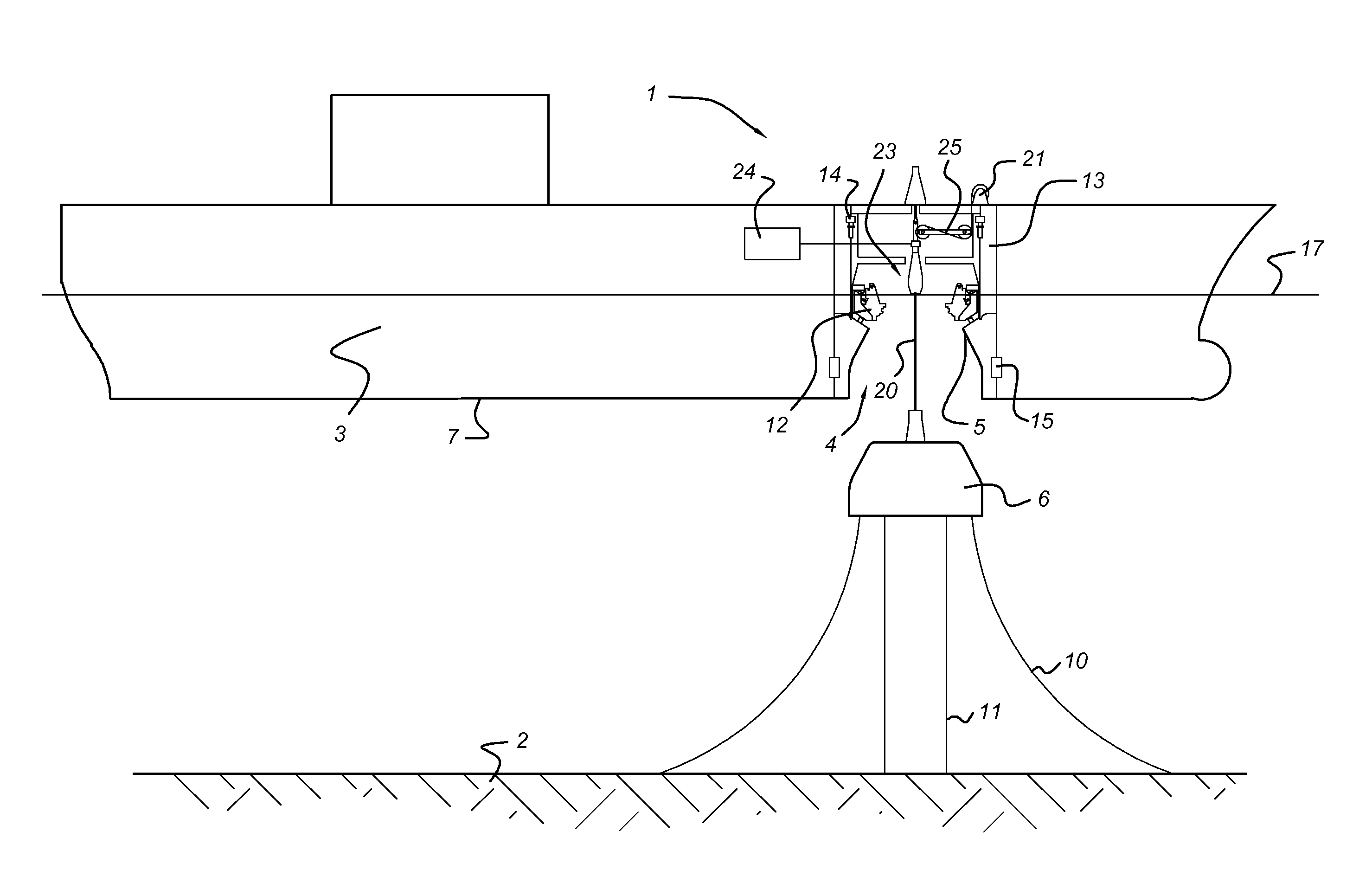
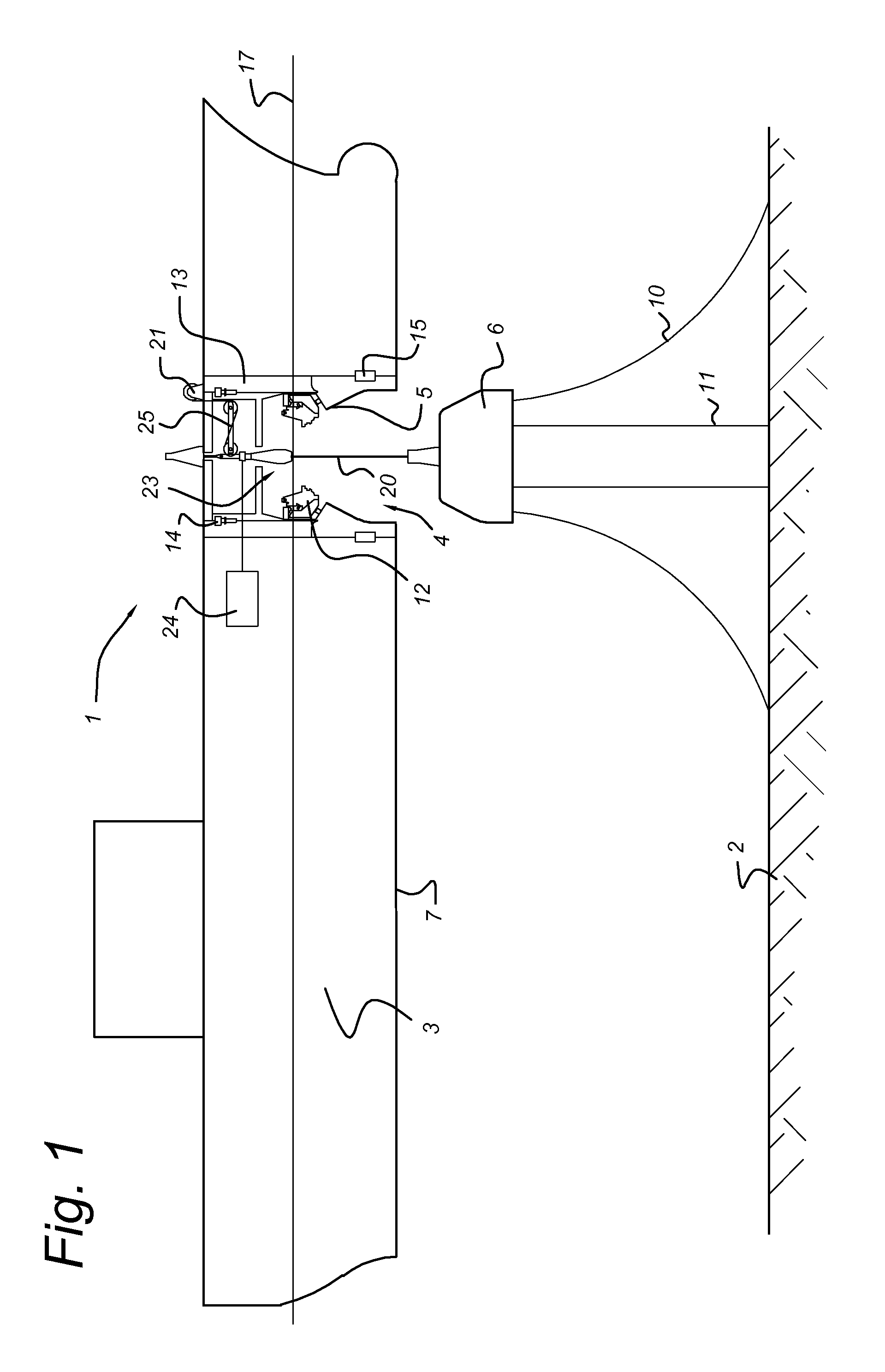
[0031]FIG. 1 shows a vessel 1, such as a FSO, a FPSO, a barge or any other vessel that is to be anchored to the sea bed 2. In the hull 3 of the vessel 1, a receiving cavity 4 defines a contact area 5 for engaging with a mooring buoy 6. The contact area 5, that is situated near keel level 7, may also comprise a differently shaped section of the hull 3, for instance a flat section for abutting against a planar connection surface of the mooring buoy 6, that may have a truncated conical shape, a cylindrical shape or any other suitably shaped contacting interface.

[0032]The mooring buoy 6 is anchored to the sea bed 2 via mooring lines 10, that may be formed of catenary chains, synthetic wire ropes, steel cables or combinations thereof. Hydrocarbon product risers 11 extend from a subsea well to the mooring buoy 6 and are to be connected to product piping and a product swivel on the vessel (not shown). The subsea well may be situated for instance 2-3 km below water level 17. The mooring buo...


PUM


Abstract

A vessel has a hull, a contact area at the hull near keel level for attaching to a structure, a lifting device and a lifting cable attached thereto and extending along a heave compensating member. The lifting cable extends along a substantially vertical lifting trajectory to a connect position below keel level. The heave compensating member includes a guide element for guiding the lifting cable and which is connected to a displacement device. The heave compensating member includes a compensator arm with a pivot end pivotally connected to a pivot point on the vessel at a predetermined transverse distance from the lifting trajectory, the cable guide element being attached to a free end of the compensator arm at or near the lifting trajectory, guiding the lifting cable in the direction of the pivot point, the arm being at or near the free end connected to the displacement device.

Description

FIELD OF THE INVENTION[0001]The invention relates to a vessel having a hull, a contact area for attaching to a structure, a lifting device on the vessel and a lifting cable attached to the lifting device and extending along a heave compensating member on the vessel and along a substantially vertical lifting trajectory to a connect position below keel level for attaching to the structure, a compensator arm with a pivot end pivotally connected to a pivot point on the vessel at a predetermined transverse distance from the lifting trajectory, a cable guide element being attached to a free end of the compensator arm at or near the lifting trajectory, guiding the lifting cable in the direction of the pivot point, the arm being at or near the free end connected to the displacement device. The invention also relates to a mooring system comprising a submerged mooring structure, and a vessel having a heave compensating system and to a method of mooring such a vessel.BACKGROUND OF THE INVENTIO...

Claims


Application Information

Patent Timeline
Patent Type & Authority Applications(United States)
IPC IPC(8): B63B21/20B63C7/02B63B22/02
CPCB63B21/20B63C7/02B63B22/02B63B21/508B63B22/023B63B39/00
Inventor WOLDRING, WILHELMUS COENRADUS JOHANNES JOZEPHUSLUNDE, PETER ALAN
Owner SINGLE BUOY MOORINGS INC
Why Eureka
Try Eureka