Image capture system, control method thereof and image capture apparatus

a technology of image capture and control method, applied in the direction of color television details, television system details, television systems, etc., can solve the problems of user motion sickness, impaired peripheral brightness and mtf, adverse effect,

Active Publication Date: 2014-02-20
CANON KK
View PDF6 Cites 57 Cited by
  • Summary
  • Abstract
  • Description
  • Claims
  • Application Information

AI Technical Summary

Problems solved by technology

Considering the image stabilization performance of a lens-interchangeable camera system, when an image stabilization shift lens arranged in the lens is greatly moved to correct a large blur during walking or the like on the wide angle side, some optical performances such as the peripheral brightness and MTF may be impaired.
However, when electronic correction is performed by the CMOS sensor, a wobbling image distortion occurs under the influence of a rolling shutter distortion, causing an adverse effect such that the user who views the movie feels motion sickness.
However, the rolling shutter distortion correction using motion vector detection has problems such as a correction error arising from a motion vector detection error, and a long processing time.
It is therefore difficult to use this correction in movie processing directly.

Method used


Image

  • Image capture system, control method thereof and image capture apparatus
  • Image capture system, control method thereof and image capture apparatus
  • Image capture system, control method thereof and image capture apparatus

Examples


first embodiment

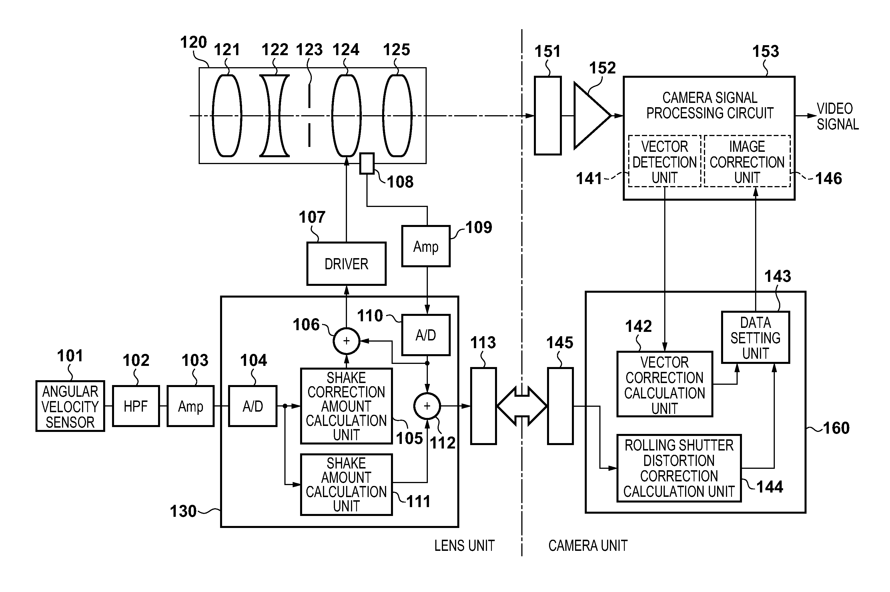
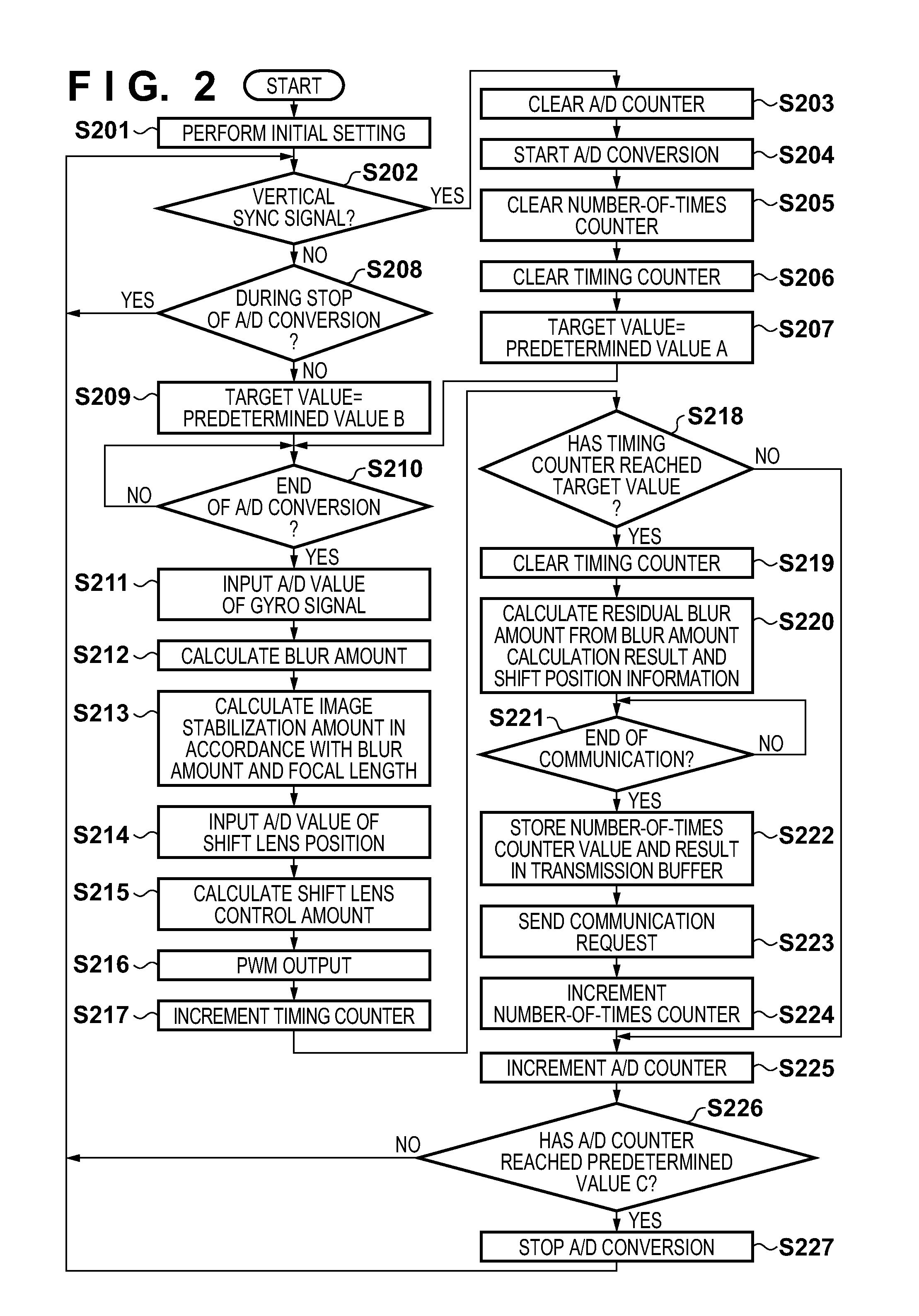
[0032]FIG. 1 is a view showing a lens-detachable image capture apparatus (image capture system) according to the first embodiment of the present invention. In FIG. 1, components 101 to 130 build up a lens unit for forming an object image, and components 141 to 160 build up a camera unit for capturing an object image.

[0033]In the lens unit, the photographing lens 120 includes the fixed lens 121, the zoom lens 122 which performs a zooming operation, the stop 123 which controls the light quantity, the shift lens (correction member) 124 which performs a shake correction operation, and the focus position correction lens (to be referred to as a focus compensation lens hereinafter) 125 using focusing and zooming. The position sensor 108 is arranged in the lens. The position sensor is arranged for correction amount detection, and detects the position of the shift lens 124.

[0034]The shake detection sensor 101 is an angular velocity sensor such as a gyro sensor. The shake detection sensor 101...

second embodiment

[0068]The second embodiment of the present invention will be described.

[0069]FIG. 7 is a view showing an image capture apparatus according to the second embodiment of the present invention. The same reference numerals as those in FIG. 1 denote blocks having the same functions, and a description thereof will not be repeated. In FIG. 7, the image capture apparatus according to the second embodiment includes a lens microcomputer 730 and camera microcomputer 760. A buffer memory 720 is arranged in the lens microcomputer 730, and stores residual blur amounts calculated a plurality of times at predetermined timings during the vertical sync period.

[0070]FIG. 8 is a flowchart showing an internal operation in the lens control microcomputer 730 in the second embodiment. FIG. 9 is a flowchart showing an internal operation in the camera control microcomputer 760. The second embodiment will be described in detail with reference to FIGS. 8 and 9.

[0071]First, processing to be executed by the lens ...

third embodiment

[0077]The third embodiment of the present invention will be described. In the first and second embodiments, a rolling shutter distortion is corrected by transmitting image stabilization data calculated in the lens to the camera. However, in the third embodiment, a gyro signal and correction lens position information are transmitted from the lens to the camera, and a residual blur is calculated in the camera body and used for rolling shutter distortion correction.

[0078]FIG. 11 is a view showing an image capture apparatus according to the third embodiment of the present invention. The arrangement is the same as that in the first embodiment, the same reference numerals as those in FIG. 1 denote blocks having the same functions, and a description thereof will not be repeated.

[0079]In FIG. 11, the image capture apparatus according to the third embodiment includes a lens microcomputer 1130 and camera microcomputer 1160. The lens microcomputer 1130 transmits, to the camera microcomputer 11...


PUM


Abstract

An image capture system including a camera body and lens unit, a shake detection unit configured to detect a shake, an image stabilization unit arranged in the lens unit to correct a blur of the object image, a correction amount detection unit configured to detect a correction amount of the image stabilization unit, a distortion correction amount calculation unit configured to calculate a distortion correction amount of an image, a motion vector detection unit arranged in the camera body to detect a motion vector from the image captured by the image sensor, and a signal processing unit configured to correct the image based on the motion vector and an output from the distortion correction amount calculation unit.

Description

BACKGROUND OF THE INVENTION[0001]1. Field of the Invention[0002]The present invention relates to a technique of realizing satisfactory image stabilization in a lens-interchangeable image capture apparatus capable of movie shooting.[0003]2. Description of the Related Art[0004]Recently, not only still cameras but also video cameras of a lens-interchangeable type have been commercialized. Along with popularization of large-screen televisions and improvement of the video quality, these products have received attention as a means for obtaining a video the user expects. As a lens to be used, these products are designed to use, for example, an interchangeable lens for a single-lens reflex camera. The user can apply the property he always has. The image stabilization performance of image capture devices such as a video camera is improving year by year, and even a large blur generated when the user walks or runs can be corrected on the wide angle side of the lens.[0005]Considering the image ...

Claims


Application Information

Patent Timeline
Patent Type & Authority Applications(United States)
IPC IPC(8): H04N5/232
CPCH04N5/2328H04N23/6811H04N23/683H04N23/685H04N23/6812
Inventor YAMAZAKI, TATSUYA
Owner CANON KK
Why Eureka
Try Eureka