
Adiabatic compressed air energy storage for automotive vehicle and energy storage method using the same

a technology of compressed air and automotive vehicles, applied in the direction of machines/engines, steam generation using hot heat carriers, transportation and packaging, etc., can solve the problem that the electric power supply of the automotive vehicle cannot be expected, and achieve the effect of increasing the density of electric power storage and increasing the electric power storage capacity

Active Publication Date: 2014-02-27
KOREA INST OF ENERGY RES
View PDF24 Cites 2 Cited by
  • Summary
  • Abstract
  • Description
  • Claims
  • Application Information

AI Technical Summary

Benefits of technology

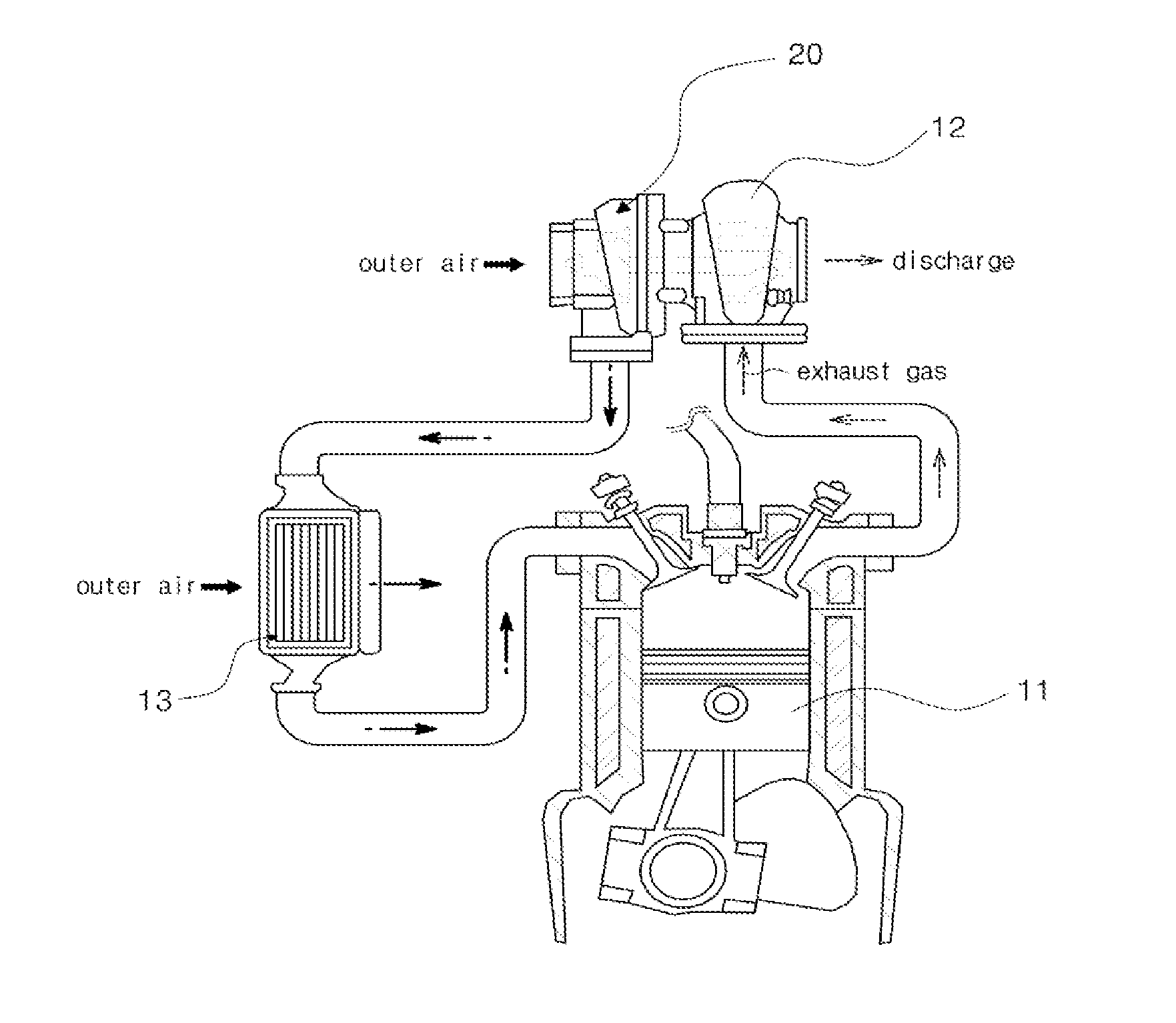
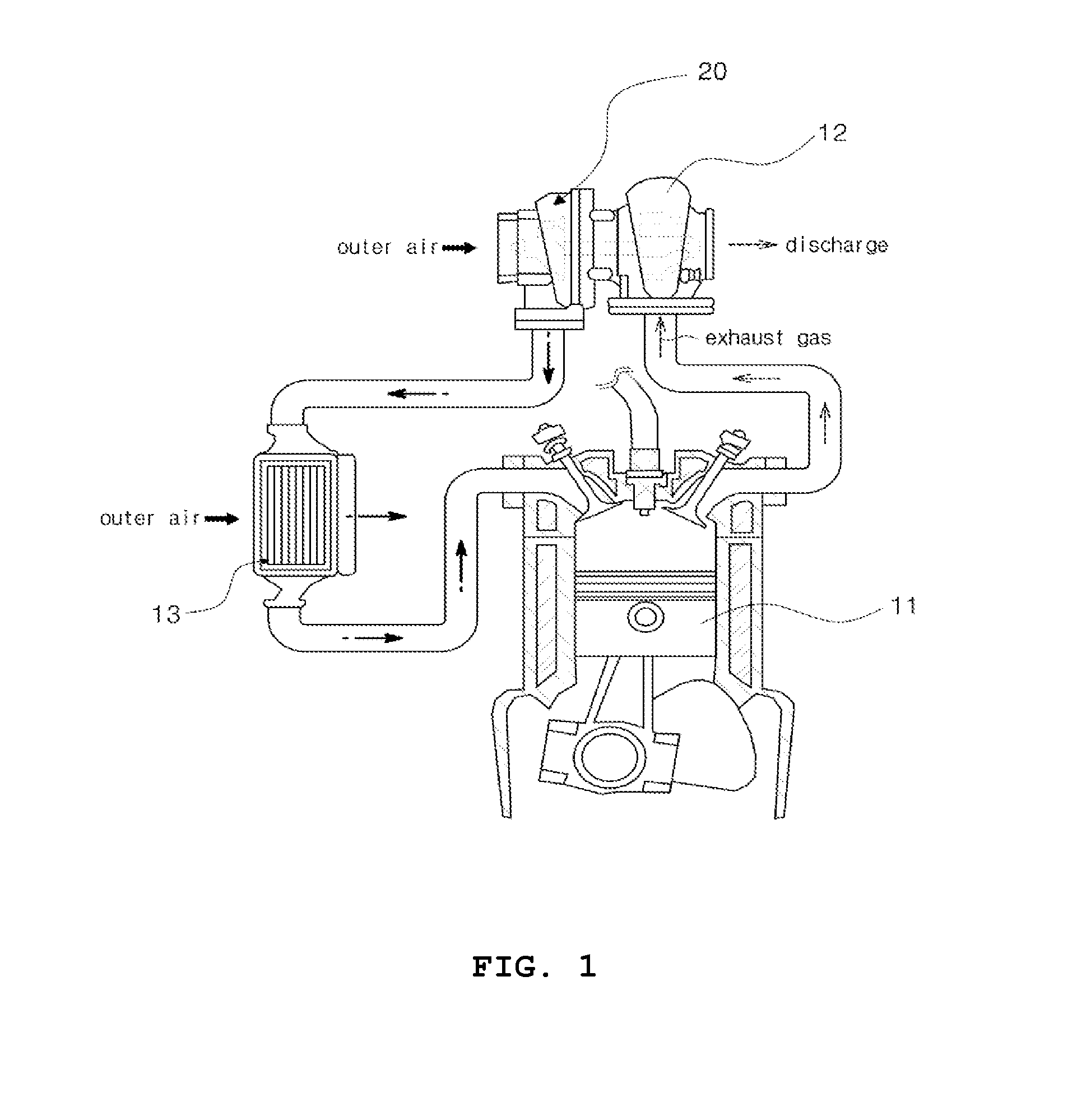
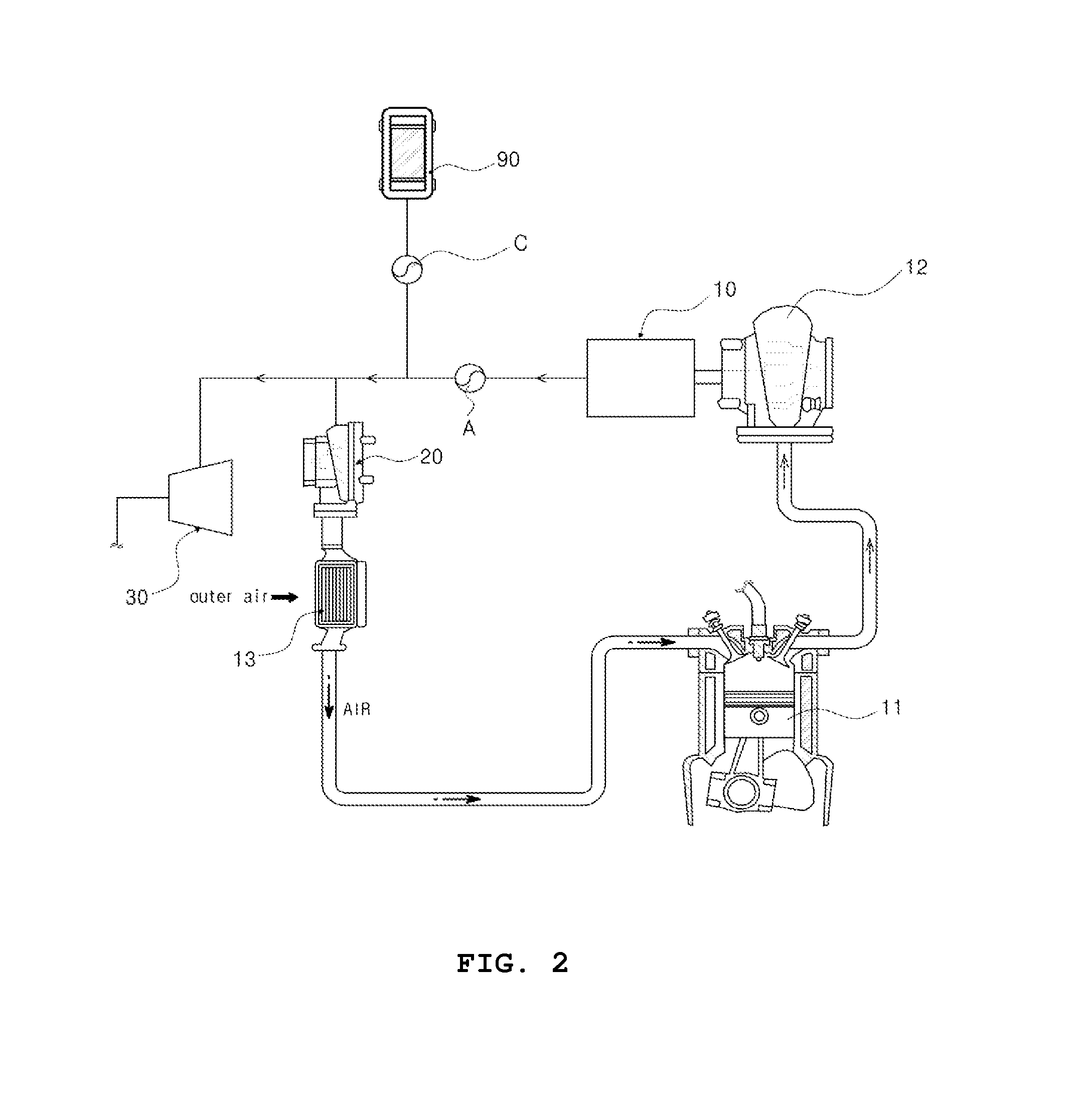
The present invention relates to an energy storage system for automotive vehicles that is designed to overcome the limitations of conventional battery storage methods. Instead, the invention uses compressed air to increase its electric power storage density, making it more efficient and easier to store energy. The invention also solves the issue of space limitation in increasing the capacity of an energy storage system due to the volume increase in proportion to the storage capacity. This is achieved by employing solar power generation and high temperature exhaust gas power generation systems commonly used in automotive vehicles, maximizing the technology application and business value effects. Additionally, the invention employs adiabatic CAES that stores and reuses the heat generated during air compression and expansion, improving the efficiency of energy storage and controlling the heat energy generated during air compression and expansion based on the operation and driving condition of the automotive vehicle. Overall, the invention provides a more effective and efficient solution for storing energy in automotive vehicles.

Problems solved by technology

In the conventional or existing automotive vehicle, when its engine is not in operation (off) while being parked or stopped, electric power supply from the automotive vehicle could not be expected because of discharge of battery power.

Method used


Image

  • Adiabatic compressed air energy storage for automotive vehicle and energy storage method using the same
  • Adiabatic compressed air energy storage for automotive vehicle and energy storage method using the same
  • Adiabatic compressed air energy storage for automotive vehicle and energy storage method using the same

Examples


Embodiment Construction

[0028]Before detailed description of various embodiments of the invention, it should be understood that the invention is not limited to the constitutions and arrangements of elements described in the following description or shown in the drawings. The invention can be embodied as various embodiments and can be put into practice through various methods. Terms indicating directions of apparatuses or elements (such as “front”, “back”, “up”, “down”, “top”, “bottom”, “left”, “right”, and “lateral”) are used to simplify description of the invention and do not represent nor mean that the apparatuses or elements have specific directions. Terms such as “first” and “second” used in this specification or the appended claims are not intended to represent or mean the relative importance or meaning.

[0029]The invention has the following features so as to achieve the above-mentioned objects.

[0030]Hereinafter, exemplary embodiments of the invention will be described in detail with reference to the a...


PUM


Abstract

Provided are an adiabatic compressed air energy storage for an automotive vehicle and an energy storage method using the same, whereby a new vehicle function is provided by using available energy from the discharged and expelled energy generated from a driven automotive vehicle or available energy source outside an automotive vehicle, and transforming the generated energy to convenient electric power and efficiently storing the energy, so that electric power can be supplied regardless of space or time constraint during the automotive vehicle in operation or parked or vehicle engine stop in view of the increase demands of electric power in automotive vehicles.

Description

BACKGROUND OF THE INVENTION[0001]1. Technical Field[0002]The present invention relates to an adiabatic compressed air energy storage for an automotive vehicle to effectively transform and store available but wasted energy from the automotive vehicle being driven or external energy source into electric power for easy use in the automotive vehicle, and an energy storage method using the same.[0003]2. Discussion of Related Art[0004]The efficiency of energy use in an automotive vehicle being in operation is roughly 30%, and remaining 65˜70% is expelled from the vehicle while a little amount of exhaust heat may be used as heat energy.[0005]An electric power car being recently spread is driven by receiving electric power from external source (Plug-in), and a hybrid car generates power by using effective power drawn from shafts depending on operation condition and stores the power into battery.[0006]Recently, we are seeing rapid changes in our life styles developed based on smart technolog...

Claims


Application Information

Patent Timeline
IPC IPC(8): F02B37/00
CPCF02B37/00F01K3/10F01K15/02F22B1/02F22B1/18Y02T10/12B60K6/28B60W10/24B60W10/30
Inventor IM, YONG HOONPARK, BYUNG SIKCHUNG, DAE HUNKANG, SAE BYULLEE, JAE YONGLEE, DONG HYUNCHOI, KYU SUNG
Owner KOREA INST OF ENERGY RES
Learn More