Internally exicted synchronous motor comprising a permanent magnet rotor with multiple corrosion protection

a synchronous motor and permanent magnet technology, applied in the direction of supporting/enclosing/casing, manufacturing dynamo-electric machines, electrical equipment, etc., can solve the problems of difficult and complicated manufacturing of glandless permanent magnet pumps, inability to protect permanent magnets from corrosive media, and high reliability of permanent magnet pumps with a long service life. , to achieve the effect of long service life, high reliability and improved reliability

Inactive Publication Date: 2014-02-27
ANDRITZ RITZ
View PDF17 Cites 15 Cited by
  • Summary
  • Abstract
  • Description
  • Claims
  • Application Information

AI Technical Summary

Benefits of technology

[0027]According to another aspect of the present invention, a pump is provided which has an electric machine according to the invention as its drive motor. Such a pump can be manufactured more cost-efficiently and also has a high level of reliability and long service life, even under tough conditions such as extremely high external pressures.

Problems solved by technology

Such high pressure differences are almost impossible to withstand using gland seals or other sealing means.
In the case of three-phase permanent-magnet machines, it is also normal, due to problems keeping them securely fastened at high rotor speeds, to not fix the magnets to the circumferential surface of the rotor, but in cutouts inside a magnetically active rotor portion.
It is therefore considered difficult and complicated to manufacture glandless, permanent-magnet pumps that have a high level of reliability and a long service life.
Since it is not possible to provide a secure seal between such single, stacked laminations, it is also not possible to protect the permanent magnets against corrosive media.
In this field of application, it is too complicated and expensive to bring the plant frequently to the surface in order to service it or replace it.
Given that very high operating pressures prevail both outside and inside the casing of electric machines in high-pressure applications, it is particularly difficult to provide secure sealing of a glandless pump rotor and its corrosion-sensitive components against the surrounding liquid medium.

Method used


Image

  • Internally exicted synchronous motor comprising a permanent magnet rotor with multiple corrosion protection
  • Internally exicted synchronous motor comprising a permanent magnet rotor with multiple corrosion protection
  • Internally exicted synchronous motor comprising a permanent magnet rotor with multiple corrosion protection

Examples


Embodiment Construction

[0036]Advantageous embodiments of the present invention shall now be described in greater detail.

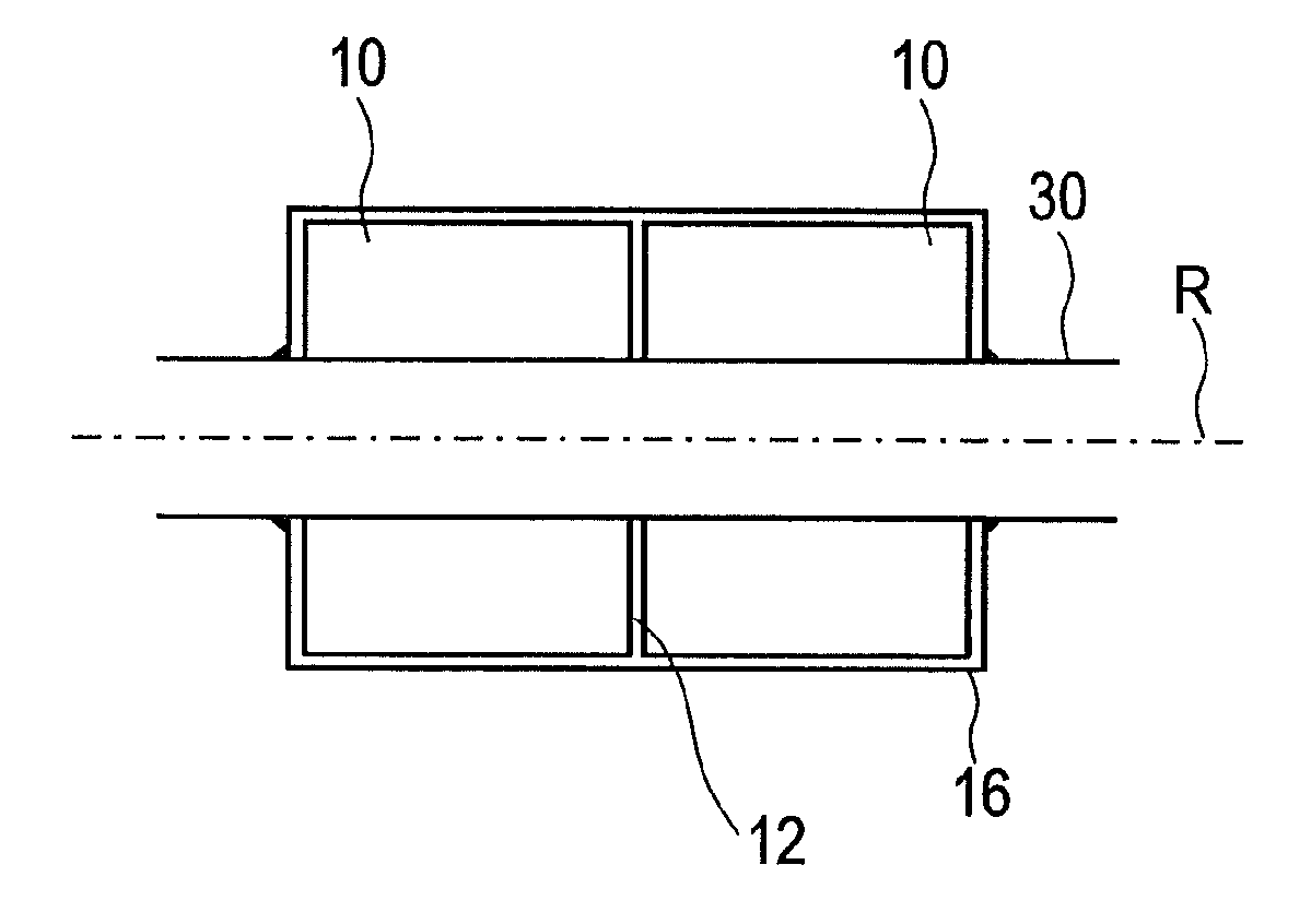
[0037]In a first embodiment, a module 10 for a rotor of an electric machine comprises a cylindrical, active part, said rotor being excited by means of permanent magnets and rotating in a liquid medium. Said active part is composed of a magnetically soft laminated stack 20 having permanent magnets 200 embedded therein.

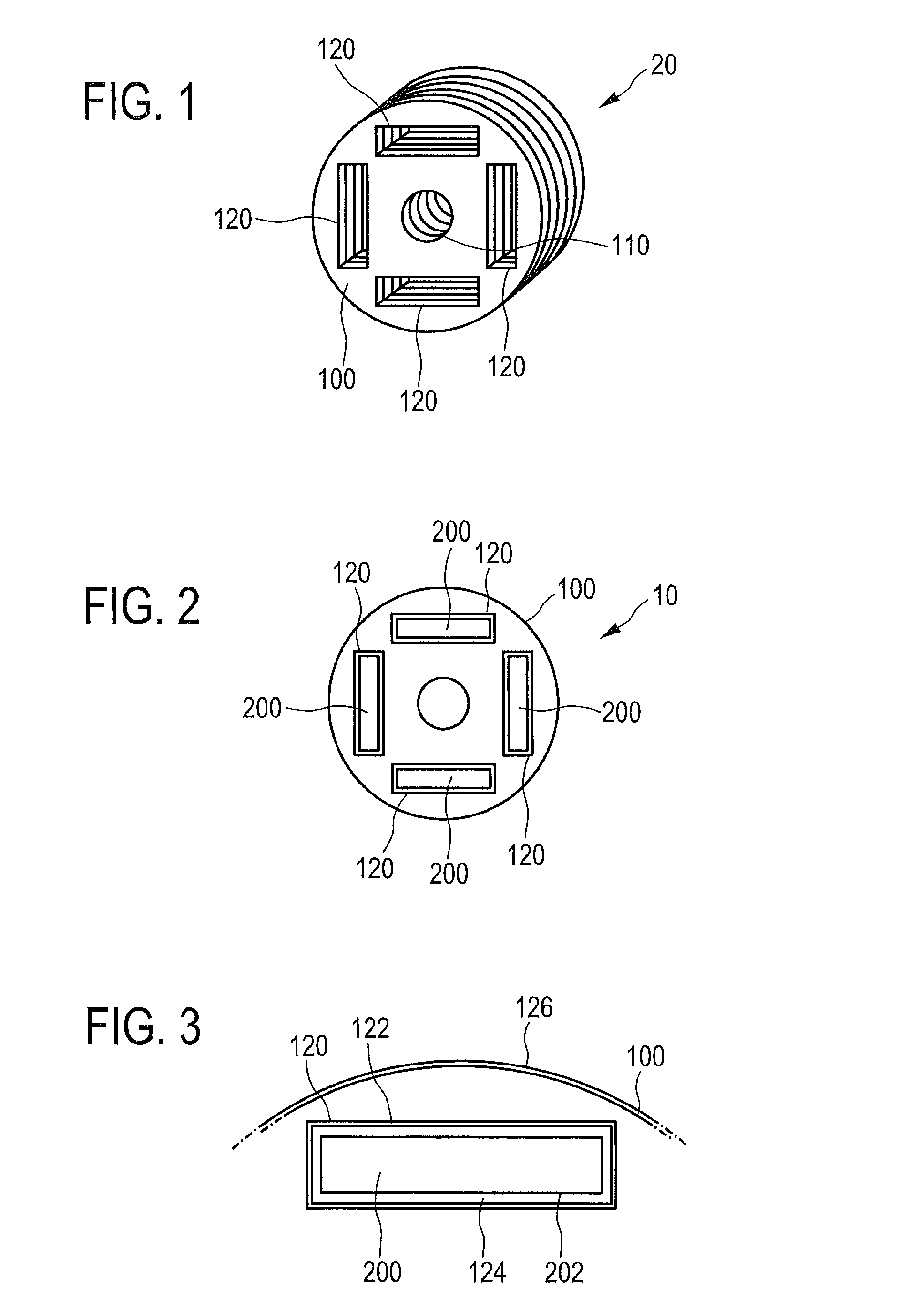
[0038]As is shown in FIG. 1, the laminated stack 20 of rotor module 10 according to the present invention comprises a stack consisting of a plurality of plates or laminations 100 made of a magnetically soft material, such as commercially available laminations in the form of transformer or dynamo laminations. These identical laminations 100 preferably have a circular outer edge and at their centre a substantially circular opening 110, coaxial with the circular outer edge, for receiving a rotor shaft 30. For torque transmission between the active rotor part or rotor module 10 ...


PUM


Abstract

A module for a rotor of an electric machine, said rotor being excited by means of permanent magnets and rotating in a liquid medium, wherein the module contains a cylindrical, active part having a plurality of circular, magnetically soft laminations which form a laminated stack and have a central opening for receiving a rotor shaft; wherein at least two permanent magnets protected against the liquid medium are arranged in at least two corresponding cutouts in the laminated stack, the cutouts being formed under a cylindrical circumferential surface of the laminated stack.

Description

CROSS-REFERENCE TO RELATED APPLICATION[0001]This application is the National Stage of International Application No. PCT / EP2011 / 000911, filed Feb. 24, 2011, which is hereby incorporated by reference.FIELD OF THE INVENTION[0002]The present invention relates to electric machines excited by means of permanent magnets. The invention relates more particularly to a rotor of an electric machine, which rotates in a liquid medium and in which the permanent magnets are embedded (internally excited electric machine).TECHNICAL BACKGROUND[0003]In the field of electric drives, it is necessary or expedient in some applications that the rotor of a three-phase machine is not located in a gas-filled space, but in a space filled with a liquid. Such rotors and the electric machines formed by them are also referred to as “glandless”. Depending on the requirements of a specific application, the rotor can run in many conceivable liquid media, for example in drinking water, in brine or in other aggressive l...

Claims


Application Information

Patent Timeline
Patent Type & Authority Applications(United States)
IPC IPC(8): H02K5/132
CPCH02K5/132H02K1/04H02K1/276H02K5/128
Inventor NEISZER, JOHANN
Owner ANDRITZ RITZ
Why Eureka
Try Eureka