Supercharge Your Innovation With Domain-Expert AI Agents!

Imaging Lens and Electronic Apparatus Having the same

a technology of electronic equipment and optical lens, which is applied in the field of optical lens and electronic equipment, can solve the problems of inability to reduce the overall system length, inability to achieve effective reduction of the system length, and relatively large gap between, so as to achieve short overall length and good optical performance

Active Publication Date: 2014-02-27
GENIUS ELECTRONICS OPTICAL CO LTD
View PDF2 Cites 13 Cited by
  • Summary
  • Abstract
  • Description
  • Claims
  • Application Information

AI Technical Summary

Benefits of technology

The technical effect of this patent is to create an imaging lens that is shorter in length but still performs well optically.

Problems solved by technology

The design proposed in the publication is unable to reduce overall system length while keeping good optical performance.
The designs proposed in these publications are unable to achieve effective reduction of the system length.
However, the entire image-side surface of the second lens element is a concave surface, resulting in relatively large gap between the second and third lens elements, which does not favor reduction of the system length.
JP2011064989, JP2012042840 discloses a conventional imaging lens, which is likewise not able to achieve reduction of the system length without compromising optical performance.
However, optical performances and imaging qualities of the imaging systems may be compromised as the overall lengths are reduced.

Method used


Image

  • Imaging Lens and Electronic Apparatus Having the same
  • Imaging Lens and Electronic Apparatus Having the same
  • Imaging Lens and Electronic Apparatus Having the same

Examples


Embodiment Construction

[0050]Before the present invention is described in greater detail, it should be noted that like elements are denoted by the same reference numerals throughout the disclosure.

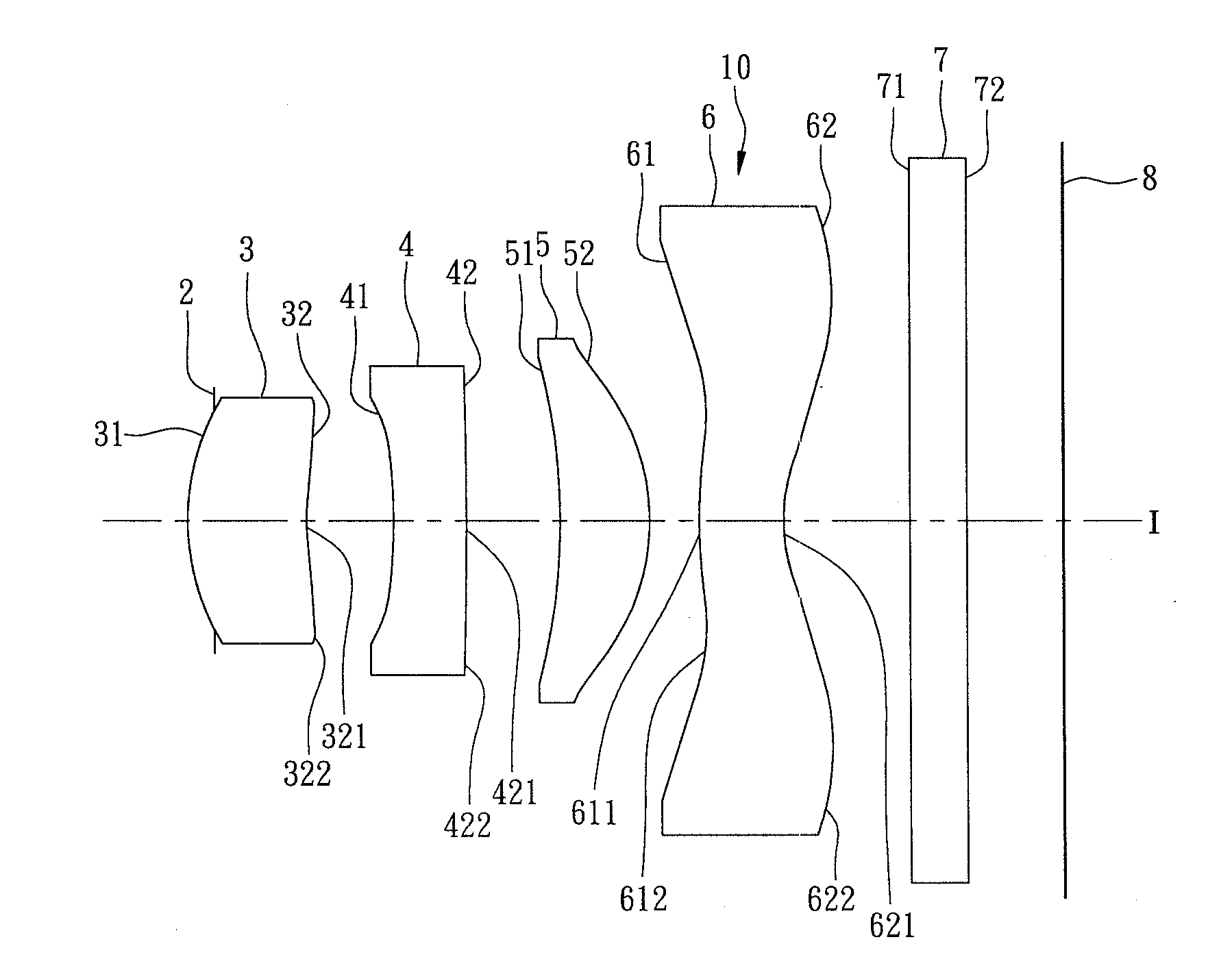
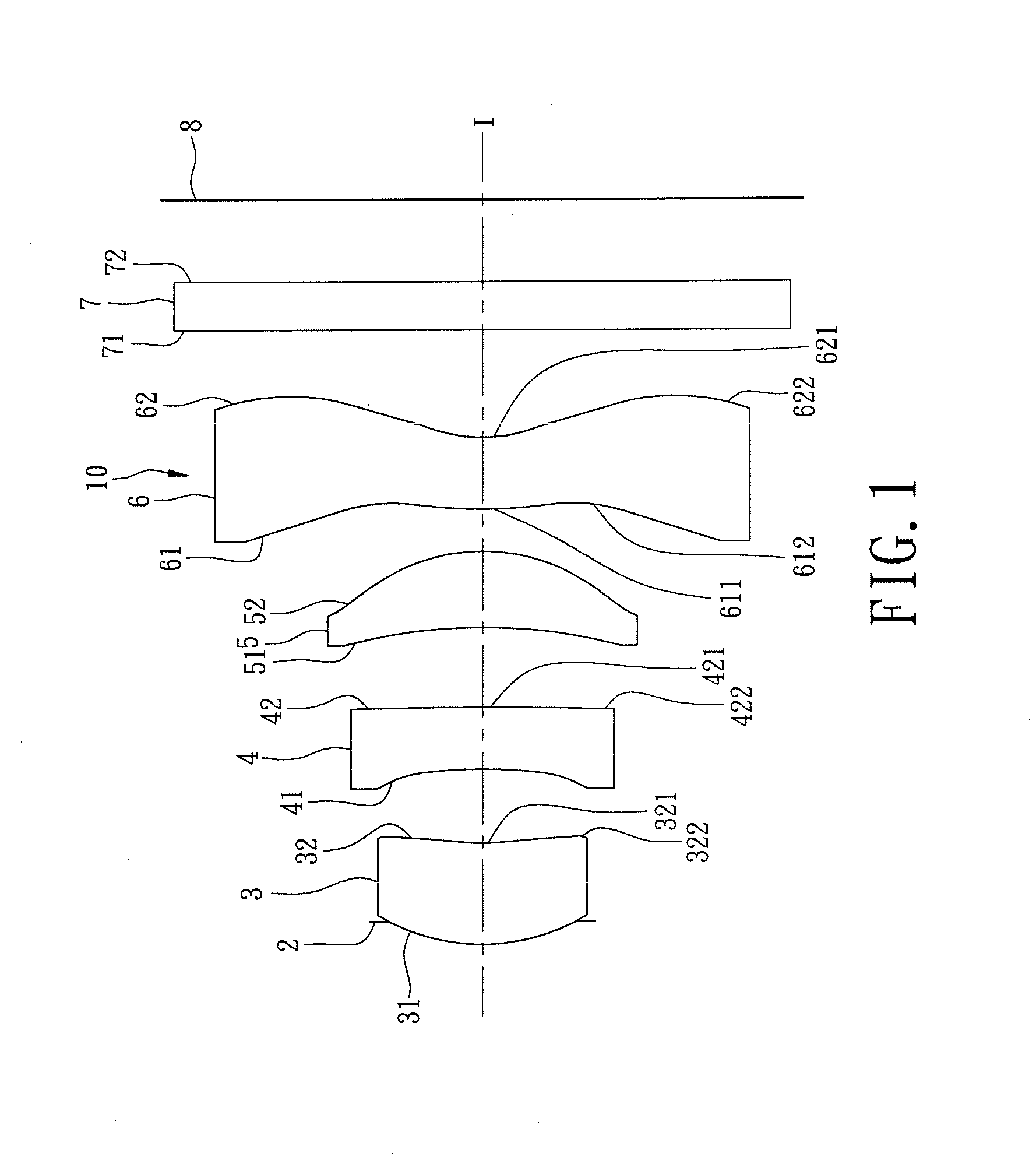
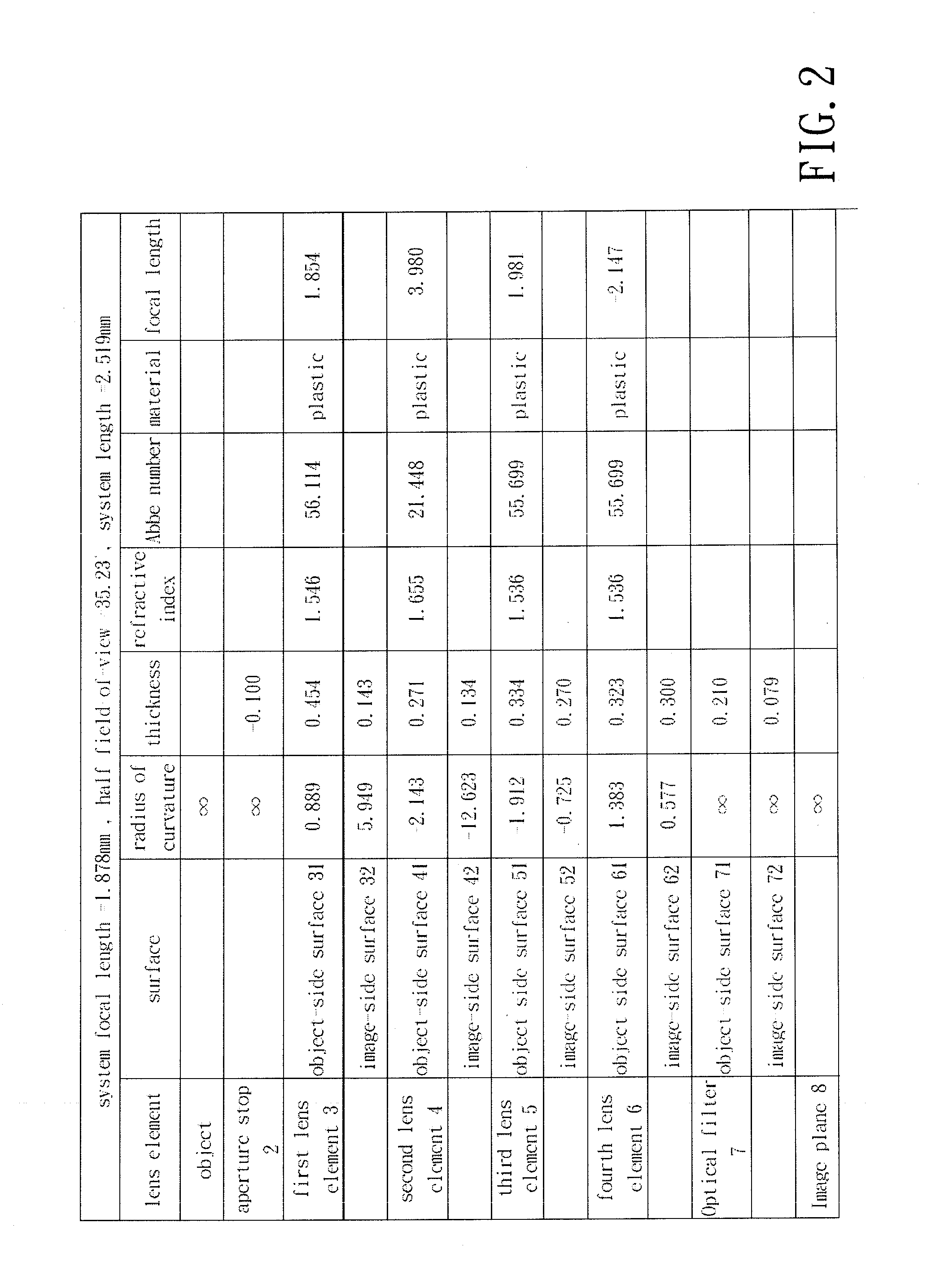
[0051]Referring to FIG. 1, an imaging lens 10 of the present invention includes an aperture stop 2, first, second, third, and fourth lens elements 3-6, and an optical filter 7 arranged in the given order along an optical axis (I) from an object side to an image side. The optical filter 7 is an infrared cut filter for selectively absorbing infrared light to thereby reduce imperfection of images formed at an image plane 8.

[0052]Each of the first, second, third, and fourth lens elements 3-6 and the optical filter 7 has an object-side surface 31, 41, 51, 61, 71 facing toward the object side, and an image-side surface 32, 42, 52, 62, 72 facing toward the image side. Light entering the imaging lens 10 travels through the aperture stop 2, the object-side and image-side surfaces 31, 32 of the first lens element 3, the o...


PUM


Abstract

An imaging lens includes first, second, third, and fourth lens elements arranged from an object side to an image side in the given order. The first lens element has a positive refractive power, and a convex object-side surface. The second lens element has a negative refractive power, and an image-side surface with a convex portion. The third lens element has a convex image-side surface. The fourth lens element has an object-side surface with a convex portion, and a curved image-side surface with a concave portion and a convex portion.

Description

CROSS-REFERENCE TO RELATED APPLICATION[0001]This application claims priority to Taiwanese Application No. 101130992, filed on Aug. 27, 2012.BACKGROUND OF THE INVENTION[0002]1. Field of the Invention[0003]The present invention relates to an imaging lens and an electronic apparatus, more particularly to an imaging lens having four lens elements and an electronic apparatus having the same.[0004]2. Description of the Related Art[0005]In recent years, as use of portable electronic devices (e.g., mobile phones and digital cameras) becomes ubiquitous, much effort has been put into reducing dimensions of portable electronic devices. Moreover, as dimensions of charged coupled device (CCD) and complementary metal-oxide semiconductor (CMOS) based optical sensors are reduced, dimensions of imaging lenses for use with the optical sensors must be correspondingly reduced without significantly compromising optical performance.[0006]US patent application publication no. 2011 / 0299178 discloses a conv...

Claims


Application Information

Patent Timeline
Patent Type & Authority Applications(United States)
IPC IPC(8): G02B3/00H04N5/225
CPCH04N5/225G02B3/0062G02B13/004H04N23/55H04N23/00G02B9/34G02B13/18
Inventor CHANG, KUO-WENLEE, POCHELO, WEI-YU
Owner GENIUS ELECTRONICS OPTICAL CO LTD
Features
  • R&D
  • Intellectual Property
  • Life Sciences
  • Materials
  • Tech Scout
  • Unparalleled Data Quality
  • Higher Quality Content
  • 60% Fewer Hallucinations
Learn More