Electric rotating machine with load dump protector

a technology of electric rotating machines and protectors, which is applied in the direction of electrical generator control, control systems, electrical apparatus, etc., can solve the problems of large voltage surge of load dump, damage to electric loads or electric components of alternators, and large increase of output voltage of alternators, so as to ensure the reliability of operation and quick suppression of voltage surges

Active Publication Date: 2014-02-27
DENSO CORP
View PDF18 Cites 15 Cited by
  • Summary
  • Abstract
  • Description
  • Claims
  • Application Information

AI Technical Summary

Benefits of technology

[0008]It is therefore an object to a structure of an electric rotating machine for automotive vehicles which is designed to quickly suppress the development of a voltage surge arising from the load dump and ensure the reliability in operation thereof.

Problems solved by technology

Accidental removal of the output terminal or disconnection of a battery terminal from the battery during a power generating mode of the alternator will result in a surge of voltage called load dump.
The peak of such surge may be as high as 100V or more depending upon the degree of output current from the alternator, which will be a factor resulting in damage to the electric loads or electric components of the alternator.
Alternatively, when the charging wire is disconnected from the output terminal of the alternator, it will result in disconnection of all the electric loads from the alternator, thus leading to a great rise in output voltage from the alternator due to the load dump.
Therefore, when the time when a voltage spike is expected not to occur is, like in the alternator taught in the above publication, waited for, it will result in an increased length of time for which an excessive voltage is appearing at the output terminal of the alternator.
This may cause the voltage which exceeds the breakdown voltage to be applied to the MOS transistor or an electric power control circuit, so that it is damaged, thus resulting in a decrease in reliability in operation of the alternator.
Alternatively, when a disconnection of the output terminal of the electric rotating machine has occurred, the load dump will result in a quick rise in level of the output voltage.

Method used


Image

  • Electric rotating machine with load dump protector
  • Electric rotating machine with load dump protector
  • Electric rotating machine with load dump protector

Examples


Embodiment Construction

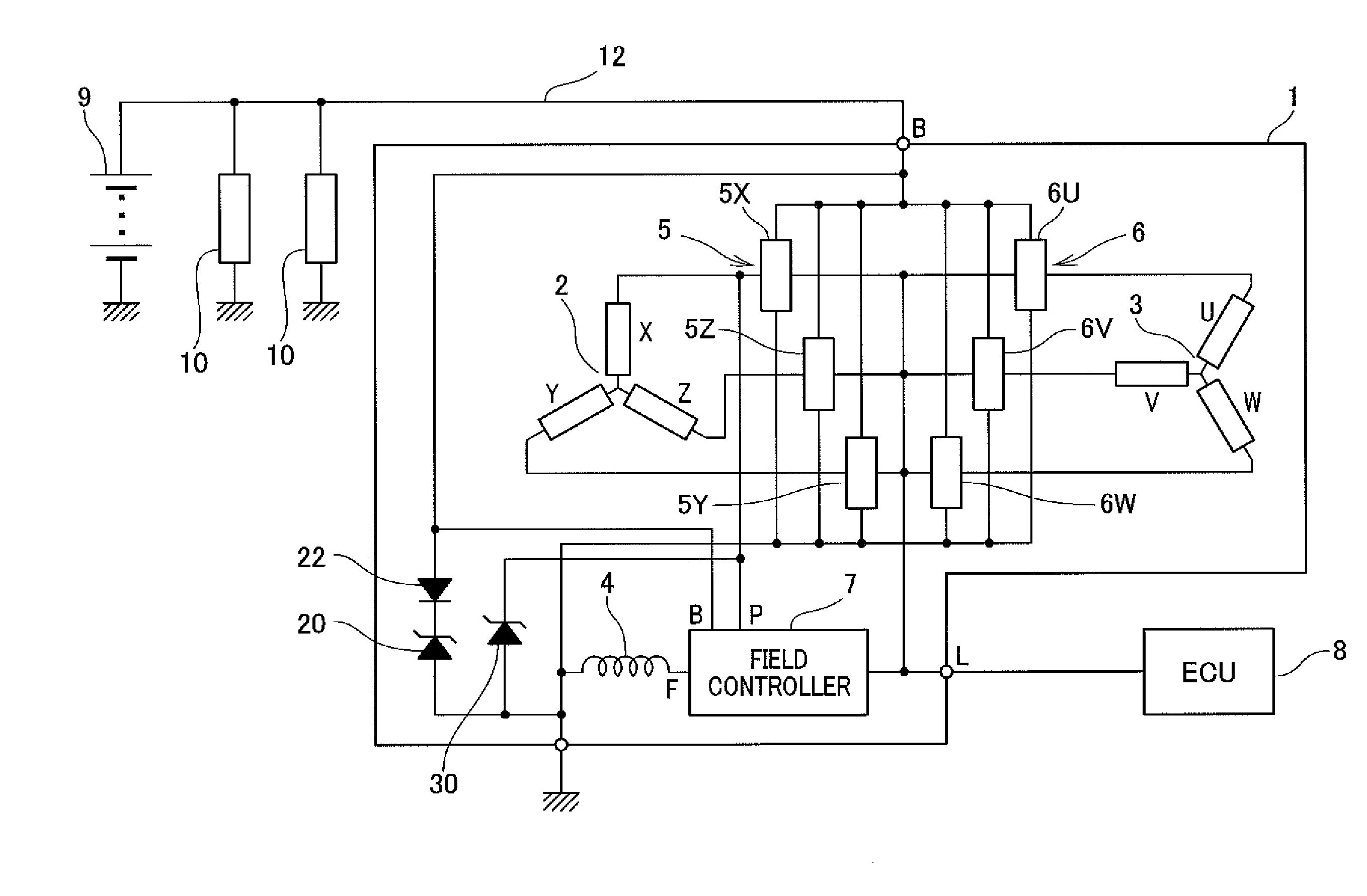
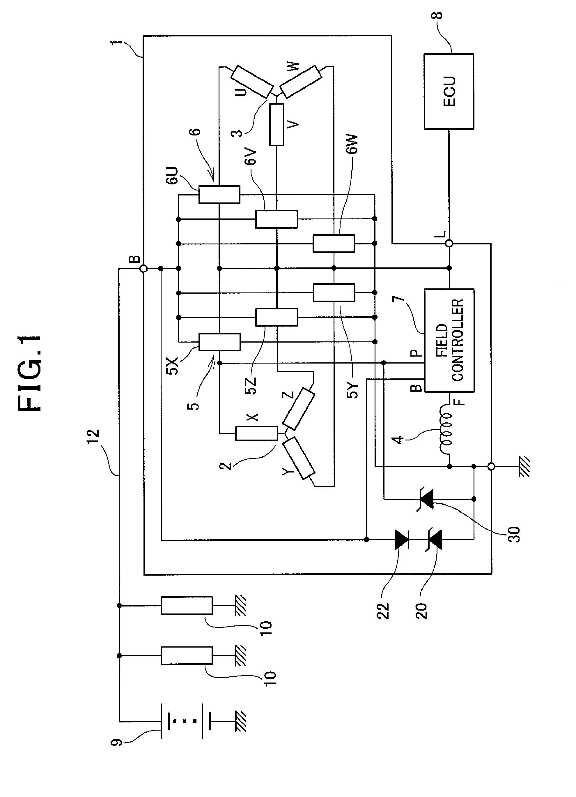
[0034]Referring to the drawings, wherein like reference numbers refer to like parts in several views, particularly to FIG. 1, there is shown an electric rotating machine 1 according to the embodiment which is designed as an electric generator or alternator for automotive vehicles.

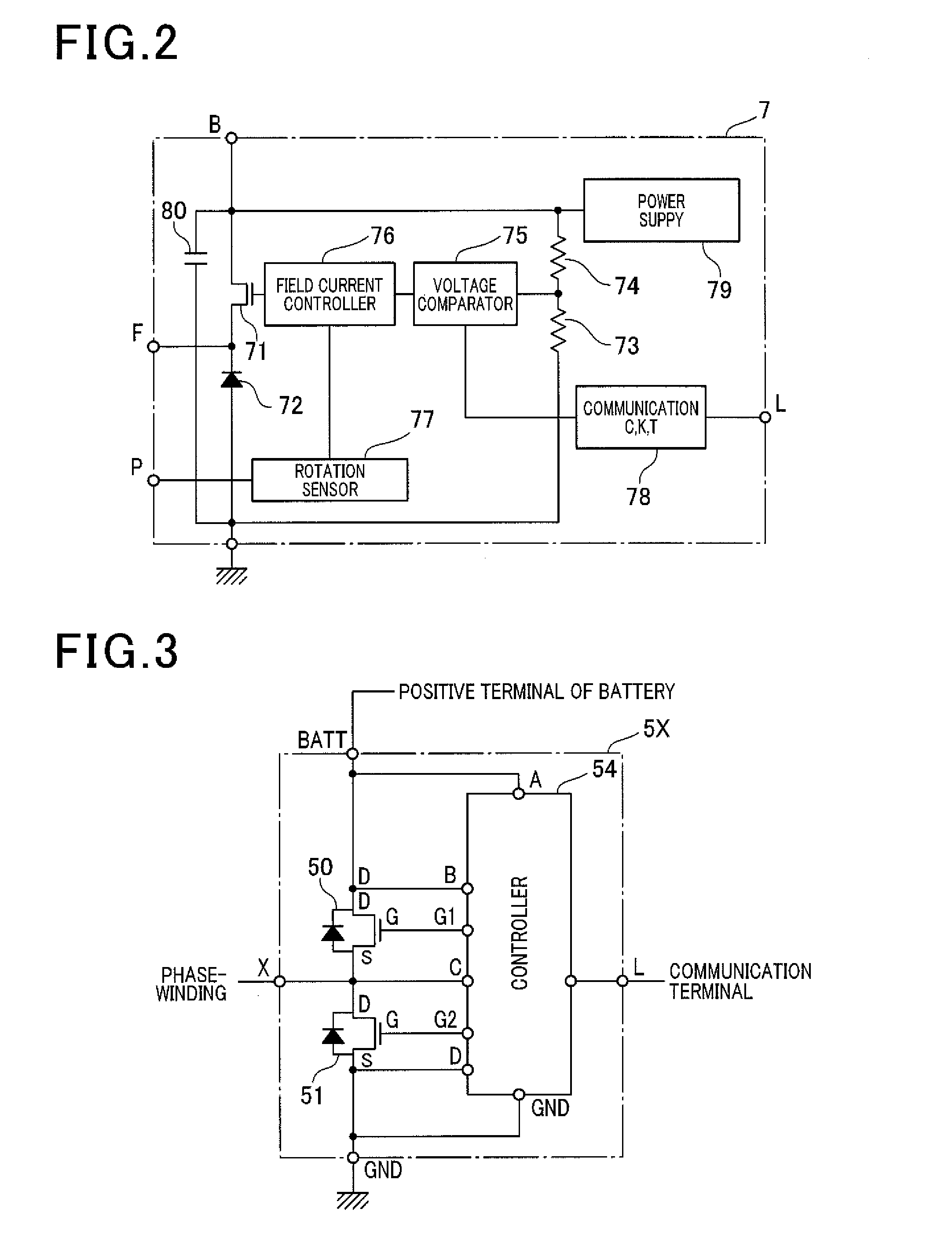
[0035]The alternator 1 is equipped with two stator windings (i.e., armature windings) 2 and 3, a field winding 4, two rectifier module groups 5 and 6, a field controller 7, Zener diodes 20 and 30, and a diode 22. Each of the rectifier module groups 5 and 6 works as a switching unit for one of the stator windings 2 and 3.

[0036]The stator winding 2 is a multi-phase winding made up of, for example, an X-phase winding, a Y-phase winding, and a Z-phase winding and wound around a stator core (not shown). Similarly, the stator winding 3 is a multi-phase winding made up of, for example, a U-phase winding, a V-phase winding, and a W-phase winding and wound around the stator core at an interval of 30° in electric ang...


PUM


Abstract

An electric rotating machine for a vehicle is equipped with a load dump protector. The load dump protector works to selectively perform a first and a second load dump protection operation to suppress a voltage surge arising from the load dump. When a rate at which an output voltage from the electric rotating machine is determined to be smaller than a given value, the load dump protector waits for stating the first load dump protection operation until the time when a voltage surge arising from changing of switching devices of a rectifier module of the electric rotating machine is expected to be suppressed and then performs the first load dump protection operation. When the rate is greater than the given value, the load dump protector immediately initiates the second load dump protection operation. This ensures the stability in eliminating the risk of a voltage surge arising from the load dump.

Description

CROSS REFERENCE TO RELATED DOCUMENT[0001]The present application claims the benefit of priority of Japanese Patent Application No. 2012-181994 filed on Aug. 21, 2012, the disclosure of which is incorporated herein by reference.BACKGROUND[0002]1. Technical Field[0003]This disclosure relates generally to an electric rotating machine which is to be mounted in automotive vehicles such as passenger vehicles or trucks.[0004]2. Background Art[0005]Typical electric generator or alternators mounted in automotive vehicles work to supply charging power or operating power to a storage battery or various types of electric loads through a charging wire coupled to an output terminal thereof. Accidental removal of the output terminal or disconnection of a battery terminal from the battery during a power generating mode of the alternator will result in a surge of voltage called load dump. The peak of such surge may be as high as 100V or more depending upon the degree of output current from the alter...

Claims


Application Information

Patent Timeline
Patent Type & Authority Applications(United States)
IPC IPC(8): H02H9/04
CPCH02H9/04H02P9/107
Inventor MARUYAMA, TOSHINORIINOKUCHI, TAKATOSHIKIMURA, ASAKANAKANISHI, MASAYA
Owner DENSO CORP
Why Eureka
Try Eureka