Receiver circuit

Active Publication Date: 2014-02-27
DENSO CORP
View PDF3 Cites 12 Cited by
  • Summary
  • Abstract
  • Description
  • Claims
  • Application Information

AI Technical Summary

Benefits of technology

The present invention provides a receiver circuit that can prevent errors caused by distortion in waveform. The circuit detects points in the signal that are likely to cause distortion, and keeps the signal level constant to prevent distortion from affecting the signal level. This results in a more reliable signal, even in systems with longer routes or higher speeds.

Problems solved by technology

In this communication system, an impedance mismatch may occur at ends of the transmission line or at connecting ends of nodes on the transmission line.
This causes oscillation in the signal waveform.
Further, the ringing may cause distortion in the waveform of the transmission signals.
However, when the waveform distortion does not sufficiently converge before the timing of judging the signal level of bits, the signal level may be erroneously judged.
The communication system configured in this way may seriously suffer from waveform distortion at an edge where the output impedance changes from low to high.
Therefore, the approach based on the related art raises a problem that a sufficient effect of preventing ringing is not necessarily ensured.

Method used


Image

  • Receiver circuit
  • Receiver circuit
  • Receiver circuit

Examples


Embodiment Construction

[0026]With reference to the accompanying drawings, hereinafter is described an exemplary embodiment of the present invention.

General Structure

[0027]In an example set forth below, the present invention is applied to an in-vehicle communication system 1 that uses CAN (Controller Area Network) as a communication protocol.

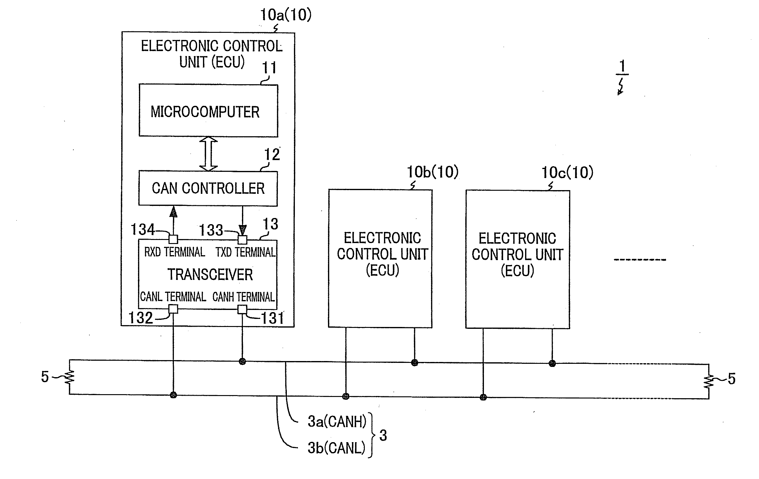
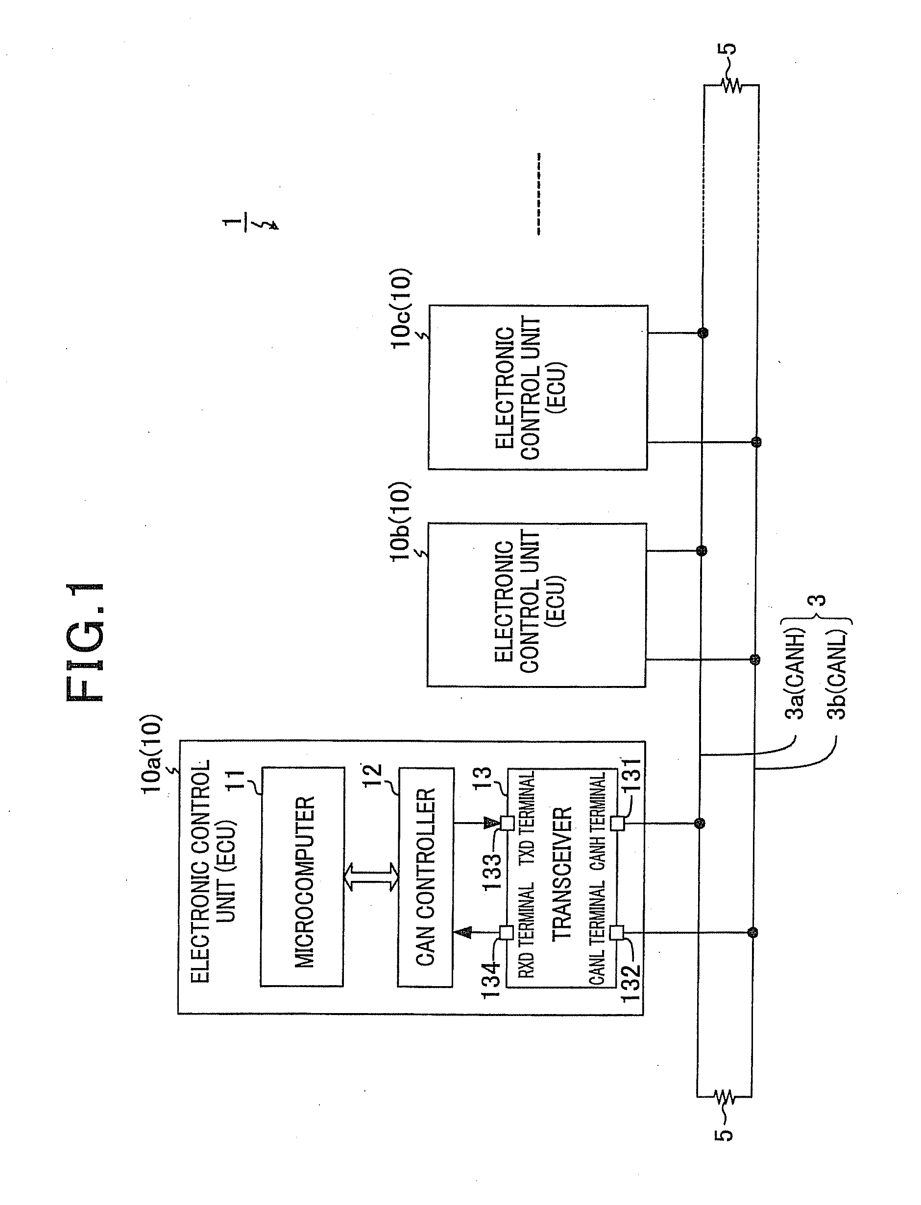
[0028]FIG. 1 is a block diagram illustrating a general configuration of the in-vehicle communication system 1. As shown in FIG. 1, the communication system 1 is configured by connecting a plurality of electronic control units 10 (10a, 10b, 10c, . . . ), which are installed in a vehicle, so as to enable intercommunication via a common transmission line 3. Each of the electronic control units 10 functions as a node. In the following description, an electronic control unit is referred to as ECU. Further, when any one of the ECUs 10 is referred to without being particularly distinguished in the following description, the ECU in question is referred to as an ECU 10.

[0029]Of...


PUM


Abstract

In a receiver circuit, a binary signal is generated based on a signal level of a received signal that has been received via a transmission line from a driver of a transmitter circuit. Then, a first stable state and a second stable state are detected based on a reference signal whose signal level changes in accordance with the received signal. In the first stable state, the received signal is stable at a first signal level. In the second stable state, the received signal is stable at a second signal level. When the first stable state is detected and the received signal is changed from the first signal level into the second signal level, the generated binary signal is retained at a signal level corresponding to the second signal level, until the second stable state is detected.

Description

CROSS-REFERENCE TO RELATED APPLICATION[0001]This application is based on and claims the benefit of priority from earlier Japanese Patent Application No. 2012-185176 filed Aug. 24, 2012, the description of which is incorporated herein by reference.BACKGROUND[0002]1. Technical Field[0003]The present invention relates to a receiver circuit that receives signals via a transmission line with a bus configuration.[0004]2. Related Art[0005]In related art, a communication system is known that transmits signals using a transmission line with a bus configuration. In this communication system, an impedance mismatch may occur at ends of the transmission line or at connecting ends of nodes on the transmission line. If such an impedance mismatch occurs, signals are reflected between these ends of the transmission line. The reflection resultantly induces ringing by which signals are permitted to repeatedly propagate on the transmission line. This causes oscillation in the signal waveform. Further, ...

Claims


Application Information

Patent Timeline
IPC IPC(8): H04B1/10
CPCH04B1/10H04B3/20
Inventor MORI, HIROYUKIKAMIKAWA, NAOKISATAKE, MASAYOSHIKISHIGAMI, TOMOHISAKOIKE, TOMOYUKI
Owner DENSO CORP
Why Eureka
Try Eureka