Inline axial flow fan

Inactive Publication Date: 2014-02-27
SANYO DENKI CO LTD
View PDF4 Cites 0 Cited by
  • Summary
  • Abstract
  • Description
  • Claims
  • Application Information

AI Technical Summary

Benefits of technology

The present invention provides an inline axial flow fan that can reduce power consumption and load noise compared to existing fans. This means that using this fan can help to save energy and reduce noise levels.

Problems solved by technology

If the stator blade shape is discontinuous, a turbulent flow may be generated in the discontinuous portion, and this may adversely influence reduction of a power consumption and a load noise.

Method used


Image

  • Inline axial flow fan
  • Inline axial flow fan
  • Inline axial flow fan

Examples


Embodiment Construction

[0023]Hereinafter, an inline axial flow fan according to the present embodiment will be described with reference to the accompanying drawings.

[0024]An axial flow fan is an air-blowing apparatus that inhales an air flow from one side of an axial direction of a rotational shaft and discharges the air flow to the other side of the axial direction by virtue of rotation of an impeller installed in a rotational shaft of a rotational driving apparatus. In the inline axial flow fan according to the present embodiment, a power consumption and a load noise can be reduced, compared to an inline axial flow fan of the related art by improving stator blade shapes of first and second flow control grids.

[0025]

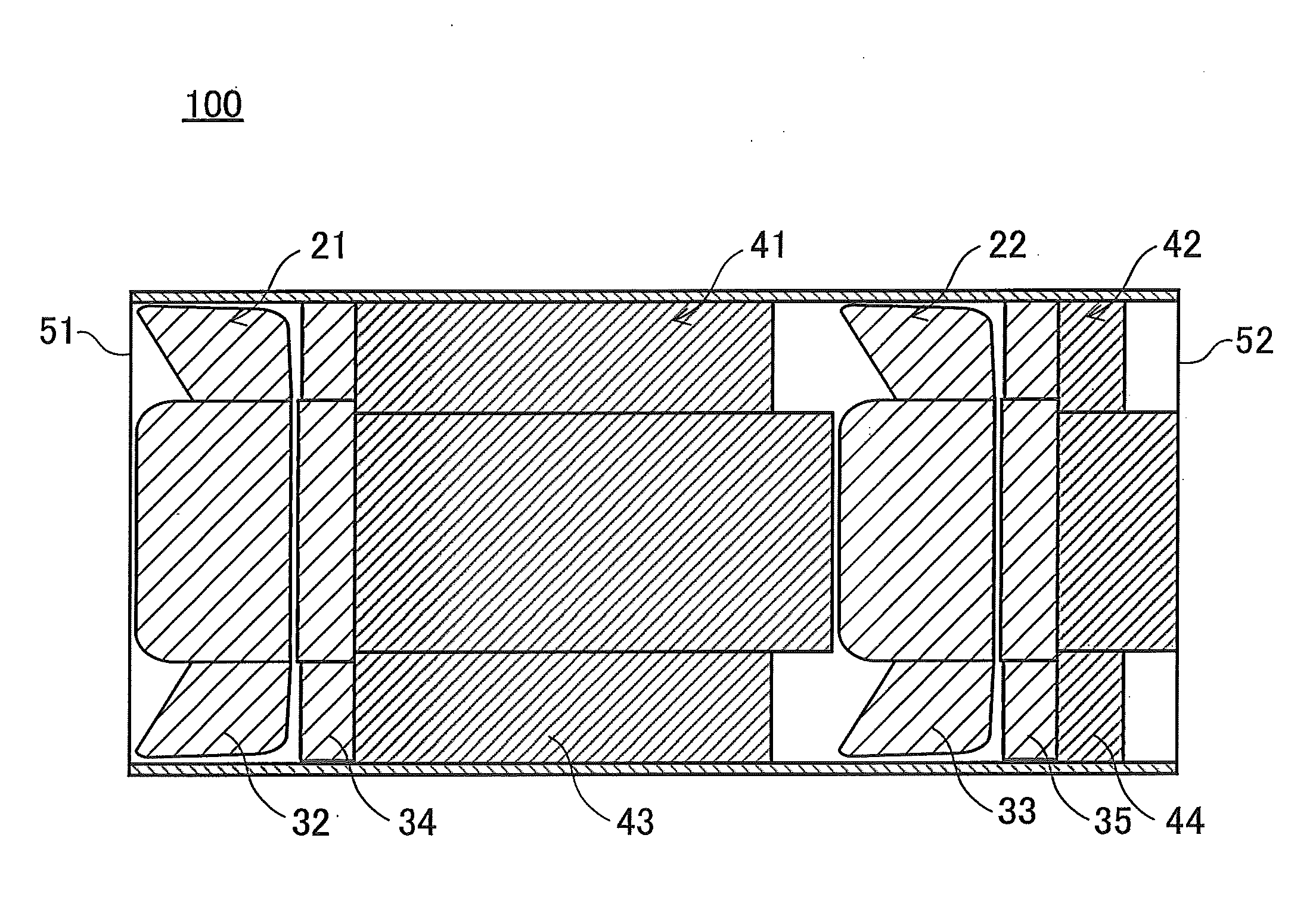
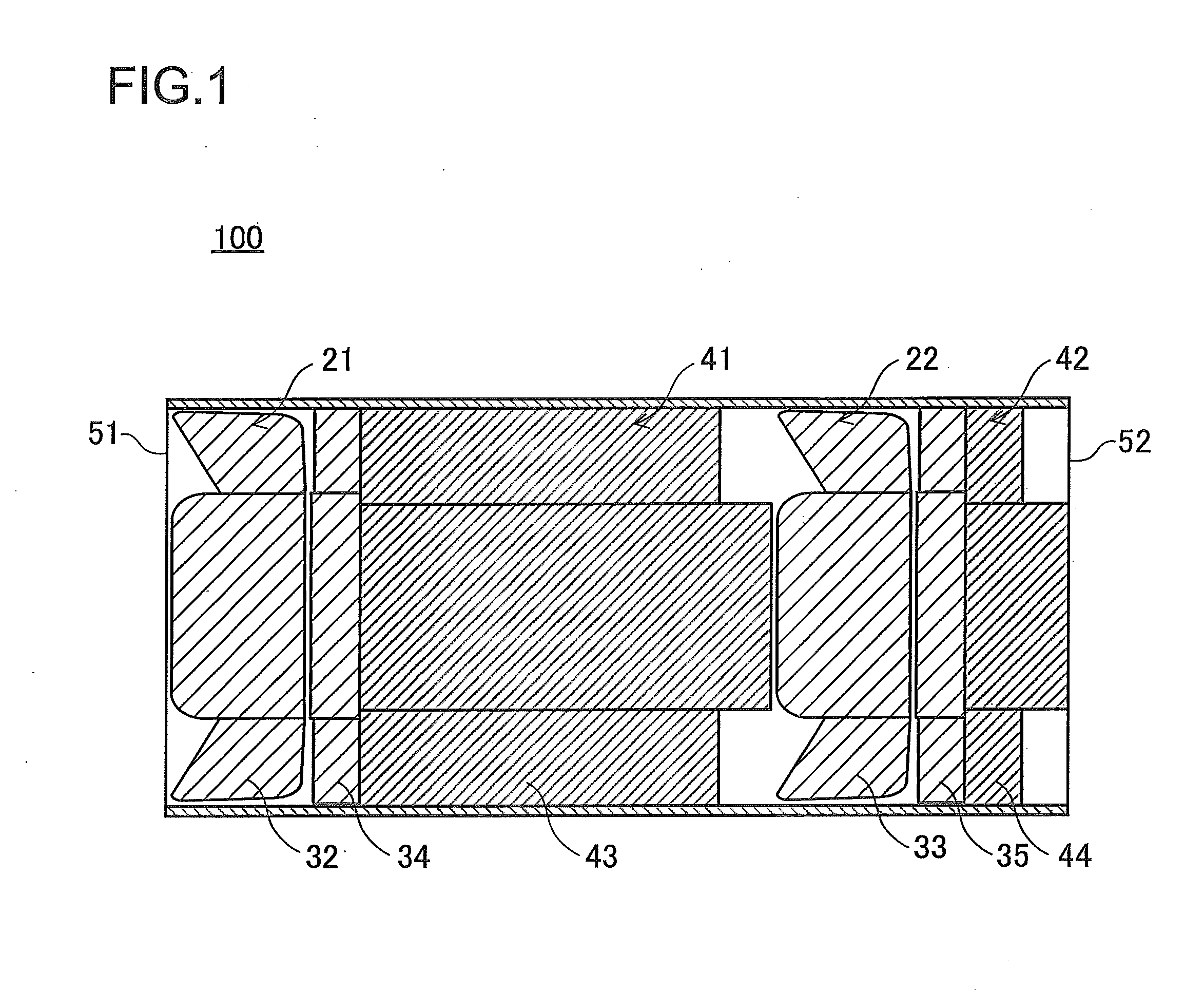
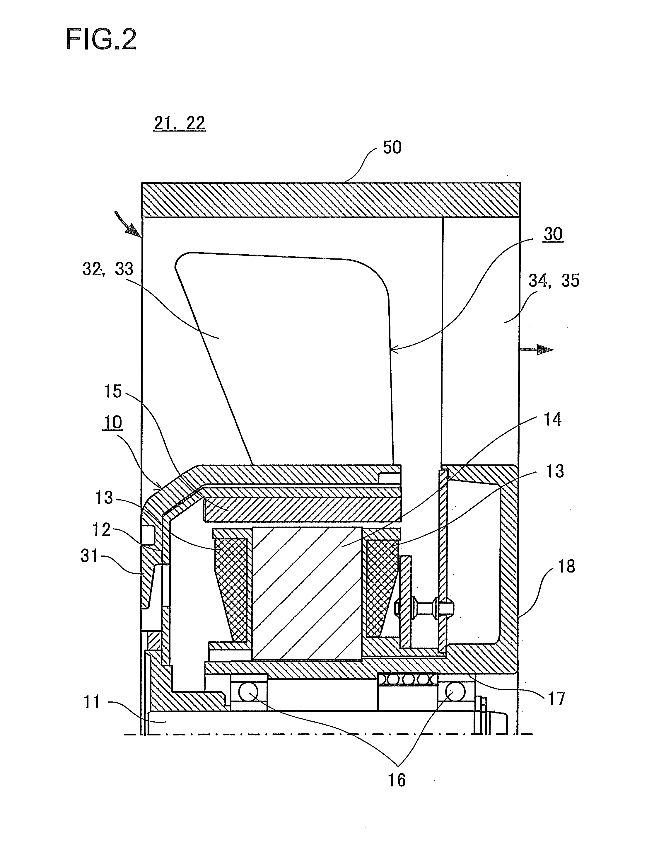
[0026]First, a configuration of the inline axial flow fan according to the present embodiment will be described with reference to FIGS. 1 and 2. FIG. 1 is a cross-sectional view illustrating an inline axial flow fan according to the present embodiment. FIG. 2 is a cross-sectional view illustra...


PUM


Abstract

There is disclosed an inline axial flow fan including at least first and second axial flow fans and arranged in an inline manner along an axial direction of a rotational shaft of a rotational driving apparatus. A first flow control grid is arranged in a gas discharge side of the first axial flow fan, and a second flow control grid is arranged in a gas discharge side of the second axial flow fan. The first flow control grid has a stator blade having a smooth circular arc leading edge shape matching a circular arc shape of the stator blade of the first axial flow fan and a trailing edge shape extending in parallel with a gas flow direction. The second flow control grid has a stator blade having a smooth circular arc shape matching a circular arc shape of the stator blade of the second axial flow fan.

Description

BACKGROUND[0001]1. Technical Field[0002]The present invention relates to an inline axial flow fan having a plurality of axial flow fans arranged in an inline manner along a rotational shaft direction of a rotational driving apparatus.[0003]2. Description of Related Arts[0004]An axial flow fan includes an impeller having a plurality of rotor blades installed in a rotational shaft of a rotational driving apparatus, a cylindrical casing that forms an axial flow along with the impeller, and a plurality of stator blades installed in an inner circumferential portion of the casing.[0005]Typically, an air-blowing property of the axial flow fan is characterized in a large air volume and a small static pressure. In order to improve the air-blowing property of the axial flow fan, various inline axial flow fans have been proposed, in which a plurality of axial flow fans is arranged in an inline manner along a rotational shaft direction of a rotational driving apparatus.[0006]As a technique rega...

Claims


Application Information

Patent Timeline
IPC IPC(8): F04D19/00
CPCF04D19/007F04D29/544F04D25/166
Inventor YEN, JUN CHIEHOOSAWA, HONAMI
Owner SANYO DENKI CO LTD
Why Eureka
Try Eureka