Pump and actuator

Inactive Publication Date: 2014-02-27
TOYOTA CENT RES & DEV LAB INC
View PDF6 Cites 4 Cited by
  • Summary
  • Abstract
  • Description
  • Claims
  • Application Information

AI Technical Summary

Benefits of technology

[0008]An advantage of the present invention is to efficiently generate a thermal transpiration flow in a pump and an actuator that use a thermal transpiration flow.
[0009]The pump that uses the thermal transpiration flow can transfer a gas, but cannot transfer a liquid, in principle. Another advantage of the present invention is to enable the transfer of a liquid in the pump that uses the thermal transpiration flow.
[0010]A pump according to the present invention includes a porous medium which has light absorption properties in a predetermined wavelength range and which has pores, and a heating unit which applies electromagnetic waves having a peak of radiant intensity in the predetermined wavelength range to a first surface of the porous medium to heat the first surface of the porous medium, wherein the first surface of the porous medium is in contact with a first space, a second surface of the porous

Problems solved by technology

However, still air has low thermal conductivity (0.02 [W/(m·K)]), and the heat of the heater is not easily transmitted to the one side of the target porous membrane, so that the heating efficiency is low.
Therefore, according to

Method used


Image

  • Pump and actuator
  • Pump and actuator
  • Pump and actuator

Examples


Example

[0050]Hereinafter, an embodiment of the present invention will be described with reference to the drawings.

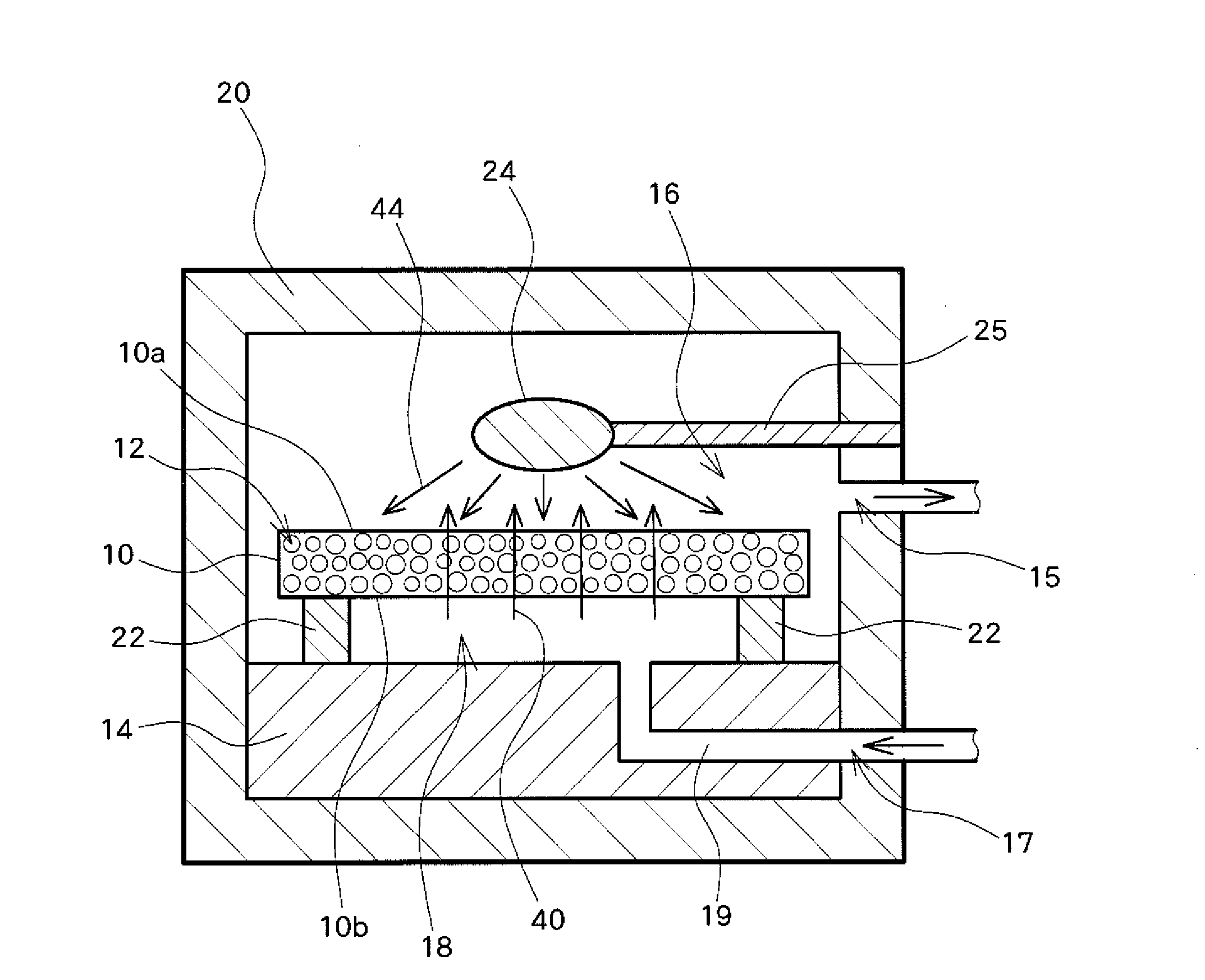
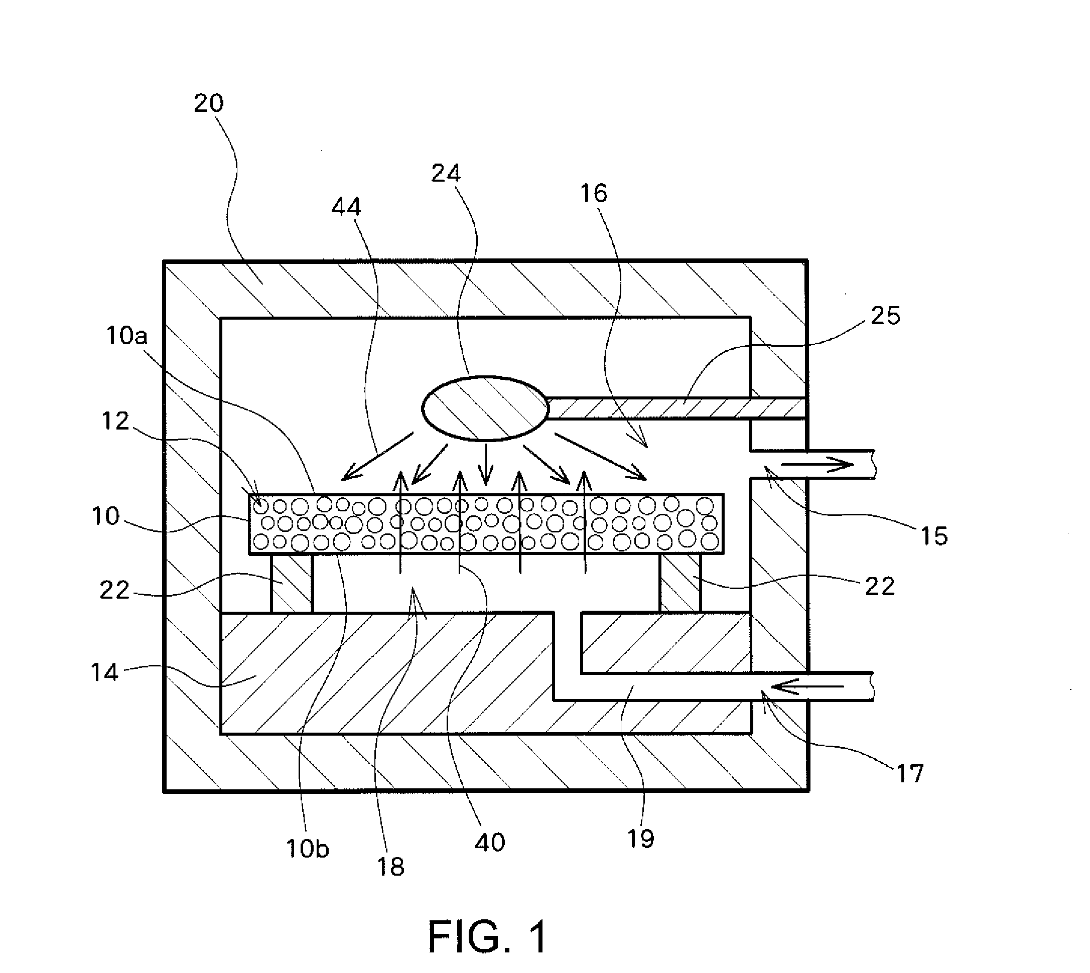
[0051]FIG. 1 is a diagram showing a general configuration of a pump according to the embodiment of the present invention.

[0052]The pump according to the present embodiment is a thermally driven molecular flow pump which can pressurize or depressurize a gas by using a thermal transpiration flow.

[0053]A porous membrane 10 disposed in a casing 20 is made of a material having a low thermal conductivity (0.2 [W / (m·K)] or less) such as a silica aerogel membrane in which a large number of pores 12 are formed in a silicon dioxide (silica, SiO2) material. A first space 16 is formed between the casing 20 and a front surface (first surface, one main surface) 10a of the porous membrane 10. A second space 18 is formed between a heat sink (heat radiation device) 14 disposed in the casing 20 and a rear surface (opposite second surface different from the first surface (one main surface)) 10b o...


PUM


Abstract

A first surface of a porous medium is in contact with a first space. A second surface of the porous medium is in contact with a second space. The first space is in communication with the second space via the pores of the porous medium. Light in a wavelength range where the material of the porous medium exhibits light absorption properties is applied to the first surface of the porous medium from a light source, so that energy of the applied light can be efficiently absorbed into the porous medium from its first surface, and the first surface of the porous medium can be efficiently heated. As a result, a thermal transpiration flow can be efficiently generated in the porous medium, and a pressure difference can be efficiently produced between the first space and the second space.

Description

PRIORITY INFORMATION[0001]This application claims priorities to Japanese Patent Application Nos. 2012-185076, filed on Aug. 24, 2012, 2013-020589, filed on Feb. 5, 2013, and 2013-151827, filed on Jul. 22, 2013, which are incorporated herein by reference in their entireties.BACKGROUND[0002]1. Technical Field[0003]The present invention relates to a pump and an actuator that use a thermal transpiration flow.[0004]2. Related Art[0005]A thermal transpiration flow is the flow specific to a rarefied gas. When there is a wall having a temperature gradient in the rarefied gas, a flow in a direction along the wall is induced from a low-temperature part to a high-temperature part. This is referred to as the thermal transpiration flow. The rarefied gas is a gas which has such few impacts between gas molecules that an equilibrium state is not maintained in a given region. A specific example of the rarefied gas has a low pressure of about 1 Pa in a region of about 1 cm3, or has a pressure substan...

Claims


Application Information

Patent Timeline
IPC IPC(8): F04B19/00
CPCF04B19/006F04B19/20
Inventor KUGIMOTO, KOKIZAKI, YOSHIMI
Owner TOYOTA CENT RES & DEV LAB INC
Why Eureka
Try Eureka