
Stent crimping methods

a technology of crimping and stent, which is applied in the field of crimping a stent to a delivery balloon, can solve the problems of time-consuming process, and achieve the effects of reducing processing time, reducing dislodgment force, and fewer steps

Active Publication Date: 2014-03-06
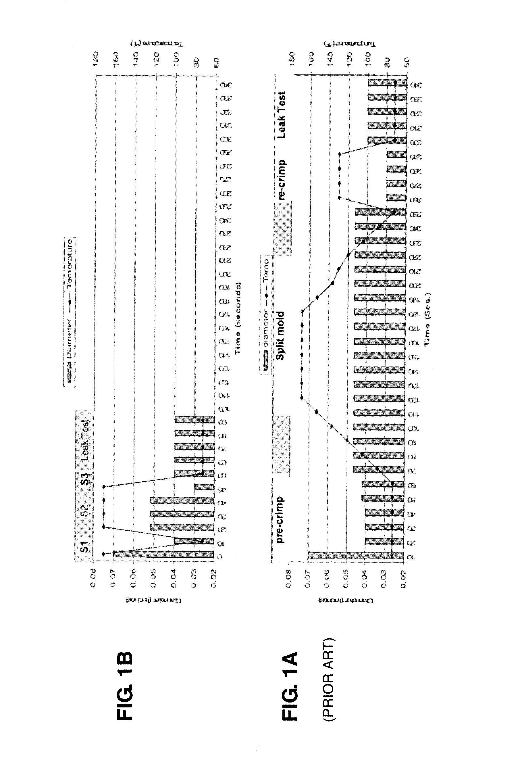
ABBOTT CARDIOVASCULAR
View PDF4 Cites 0 Cited by
  • Summary
  • Abstract
  • Description
  • Claims
  • Application Information

AI Technical Summary

Benefits of technology

Significantly reduces processing time by up to 70% while increasing dislodgment force, maintaining the desired stent profile and ensuring reliable delivery through tortuous pathways without stent or balloon damage.

Problems solved by technology

This process is time consuming and requires the use of multiple machines for performing the process.

Method used


Image

  • Stent crimping methods

Examples


Embodiment Construction

[0030]For purposes of this disclosure, a “stent” means an open-walled tubular body of interconnected, spaced-apart struts with gaps between adjacent stent struts. The struts may form rings having a serpentine wave pattern of opposed turns and which are longitudinally spaced apart and connected by links. The stent, when crimped to a balloon undergoes a process of plastic deformation from a starting or manufactured diameter to a final or crimped diameter. The stent is expanded to a deployed diameter by being plastically deformed by expansion of the balloon.

[0031]A stent having a pattern as described in U.S. Pat. No. 6,312,459 or U.S. Pat. No. 179,867 may have a starting, or manufactured outer surface diameter of 0.07 in. The stent is made from a metal or metal alloy. The stent may be crimped to a non-compliant balloon made from PEBAX material. When deployed the stent has a nominal 3 mm (0.118 in) outer diameter and 18 mm (0.708 in) length. For purposes of this disclosure, this stent w...


PUM


Abstract

A process for crimping stents includes a multi-stage process producing a desired stent retention and crimped profile in a reduced amount of time. The process achieves results by utilizing particular combinations of heat and pressure during the crimping process, which was found to produce the desired results.

Description

BACKGROUND OF THE INVENTION[0001]1. Field of the Invention[0002]The present invention relates to drug-eluting medical devices; more particularly, this invention relates to processes for crimping a stent to a delivery balloon.[0003]2. Background of the Invention[0004]A known stent retention process consists of three operations, stent crimp, split mold and stent press. Stent crimp is the process by which the stent is placed on the catheter. First the stent is placed on a pre-crimp mandrel and placed in the crimp machine. The crimp machine closes onto the stent applying radial force causing the stent's diameter to be reduced to that of the pre-crimp mandrel. The pre-crimp mandrel diameter is selected based on the delivery systems folded balloon profile. After pre-crimp, the stent is removed from the mandrel and placed on a balloon delivery system, balloon catheter, or delivery system. The balloon catheter is placed into the crimp machine and radial force applied to reduce the diameter ...

Claims


Application Information

Patent Timeline
Patent Type & Authority Applications(United States)
IPC IPC(8): A61F2/95
CPCA61F2/95A61F2/958A61F2/9522A61F2/9524A61F2/9526Y10T29/49927Y10T29/53952
Inventor KNOTT, BOYD V.KADAKIA, SAMITORTEGA, LEOPOLDA
Owner ABBOTT CARDIOVASCULAR
Learn More