Stent crimping methods

a technology of crimping and stents, applied in the field of drugeluting medical devices, can solve the problems of time-consuming process, and achieve the effects of reducing processing time, reducing dislodgment force, and fewer steps

Active Publication Date: 2013-12-03
ABBOTT CARDIOVASCULAR
View PDF14 Cites 17 Cited by
  • Summary
  • Abstract
  • Description
  • Claims
  • Application Information

AI Technical Summary

Benefits of technology

[0010]The invention provides a process and apparatus for crimping a stent to a balloon that reduces the processing time, involves fewer steps and produces an increased dislodgment force for a stent crimped to a balloon. Prior processes for crimping a stent to a balloon have involved a pre-crimp process, followed by a balloon pressurization step within a mold. This step was then followed by a final crimp stage where the stent is crimped to a final diameter. This process is time consuming and requires the use of multiple machines for performing the process. Moreover, the dislodgment force was in need of improvement to facilitate better retention of the stent on the balloon during delivery to a target site in a vessel.
[0011]It was discovered, unexpectedly, that when parameters of the crimping process are varied in a particular manner, the same retention and target outer diameter profile for the catheter could be achieved without reducing yield, i.e., no increased rate of stent or balloon damage for a batch run using the new process and dislodgment force may be increased without introducing other undesired qualities. In tests conducted using the new process the processing time could be reduced by about 70%, without reducing yield and with increased dislodgment force for the crimped stent and balloon.
[0012]Accordingly, the advantages of the process according to the invention may be described as two-fold: a significant reduction in the duration of a crimping process, primarily by a reduction in the dwell time during pre-crimp, encapsulation, and final crimp; and increased dislodgment force without effecting the stent profile or deliverability of the stent through a tortuous pathway.
[0013]The process may be described as having three stages, which may proceed in a more or less continuous manner. Stage 1 is a pre-crimp stage. The stent is loaded onto a mandrel and placed in a crimping machine where an iris type mechanism closes crimping jaws or blades onto the stent and reduces the profile of the stent down to a specified dimension. In Stage 2, the stent is loaded onto the balloon catheter delivery system and placed back into the crimping machine where the iris type mechanism closes down to a specified dimension, the catheter is pressurized and the distal end of the delivery system is heated for a specific amount of time to cause pillowing of the balloon between stent struts. In Stage 3, the iris type mechanism may then open and closes to specified dimensions to decreasing the stent dimension or profile, which causes increased mechanical interaction between balloon and stent. Opening and closing the iris type mechanism onto the stent several times may be performed in order to work the stent material, to reduce recoil, decrease system profile and further increase the mechanical interaction between balloon and stent.
[0014]In an alternate embodiment of Stage 3, the iris-type mechanism does not increase in diameter. Rather, the iris-type mechanism closes from the Stage 2 iris diameter to a smaller, Stage 3 diameter. This Stage 3 diameter may be less than the final crimp diameter. Catheter pressurization may also be added to Stage 3 processing to help retain / increase the pillowing at the smaller dimension, thereby further increasing the mechanical interaction between balloon and stent. Adding catheter pressurization prior to or during the iris type mechanism reaching the final specified dimension or profile may also increase the mechanical interaction between balloon and stent above just pressurizing the system at the specified dimension for the specified dwell time. By pressurizing during the closing of the iris, for example, the stent and balloon position is fixed or constrained relative to each other, which allows for an existing imprint of the stent on the balloon (formed during stage 2) to be substantially retained or unaltered when the stent is reduced in diameter, which increases the mechanical interaction.
[0024]Step iv may include placing a sheath having an inner diameter of about 25% greater than the stent first diameter over the stent to protect a coating on the stent, wherein the sheath has a radial stiffness such that the presence of the sheath over the stent provides the up to about 25-30% of the first diameter restraint on stent expansion during step iv. This range may be increased and the sheath may be further aided by the crimper blades to provide a restraint on stent expansion to facilitate the interlocking of balloon material with stent struts.

Problems solved by technology

This process is time consuming and requires the use of multiple machines for performing the process.

Method used


Image

  • Stent crimping methods
  • Stent crimping methods

Examples


Embodiment Construction

[0030]For purposes of this disclosure, a “stent” means an open-walled tubular body of interconnected, spaced-apart struts with gaps between adjacent stent struts. The struts may form rings having a serpentine wave pattern of opposed turns and which are longitudinally spaced apart and connected by links. The stent, when crimped to a balloon undergoes a process of plastic deformation from a starting or manufactured diameter to a final or crimped diameter. The stent is expanded to a deployed diameter by being plastically deformed by expansion of the balloon.

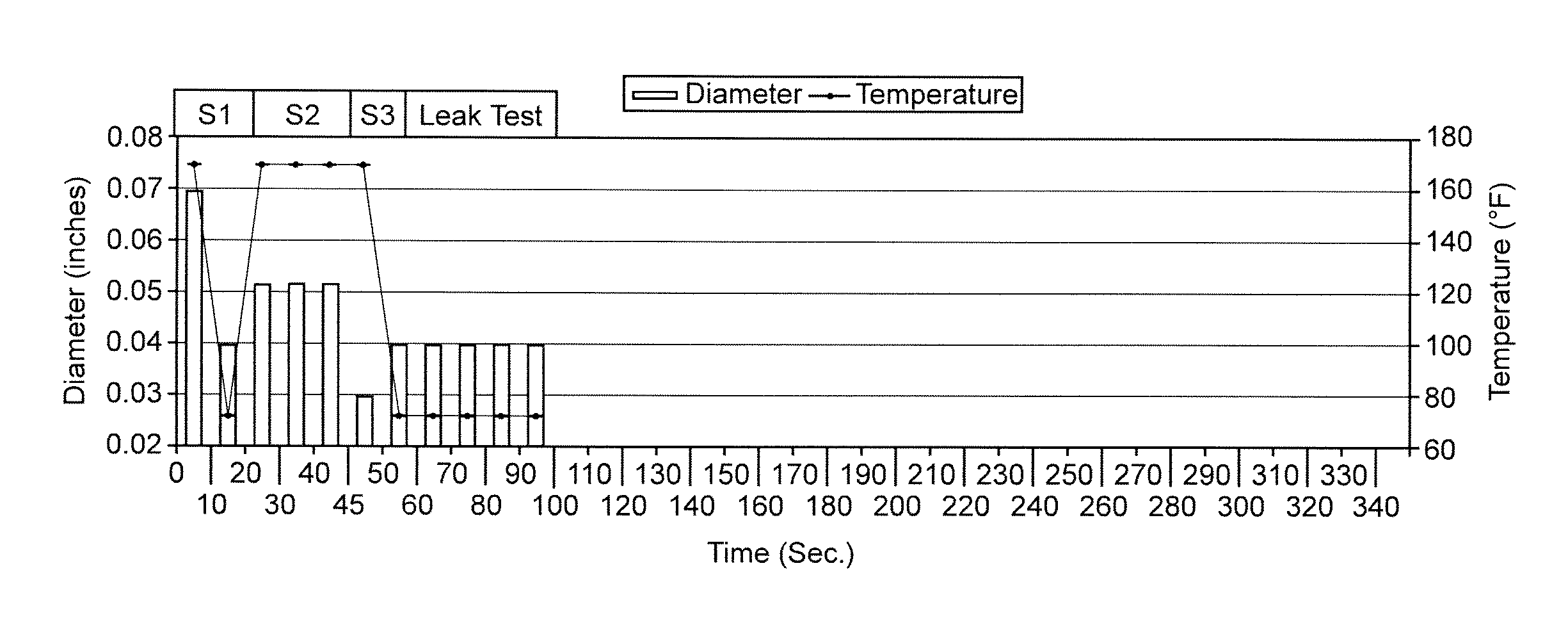
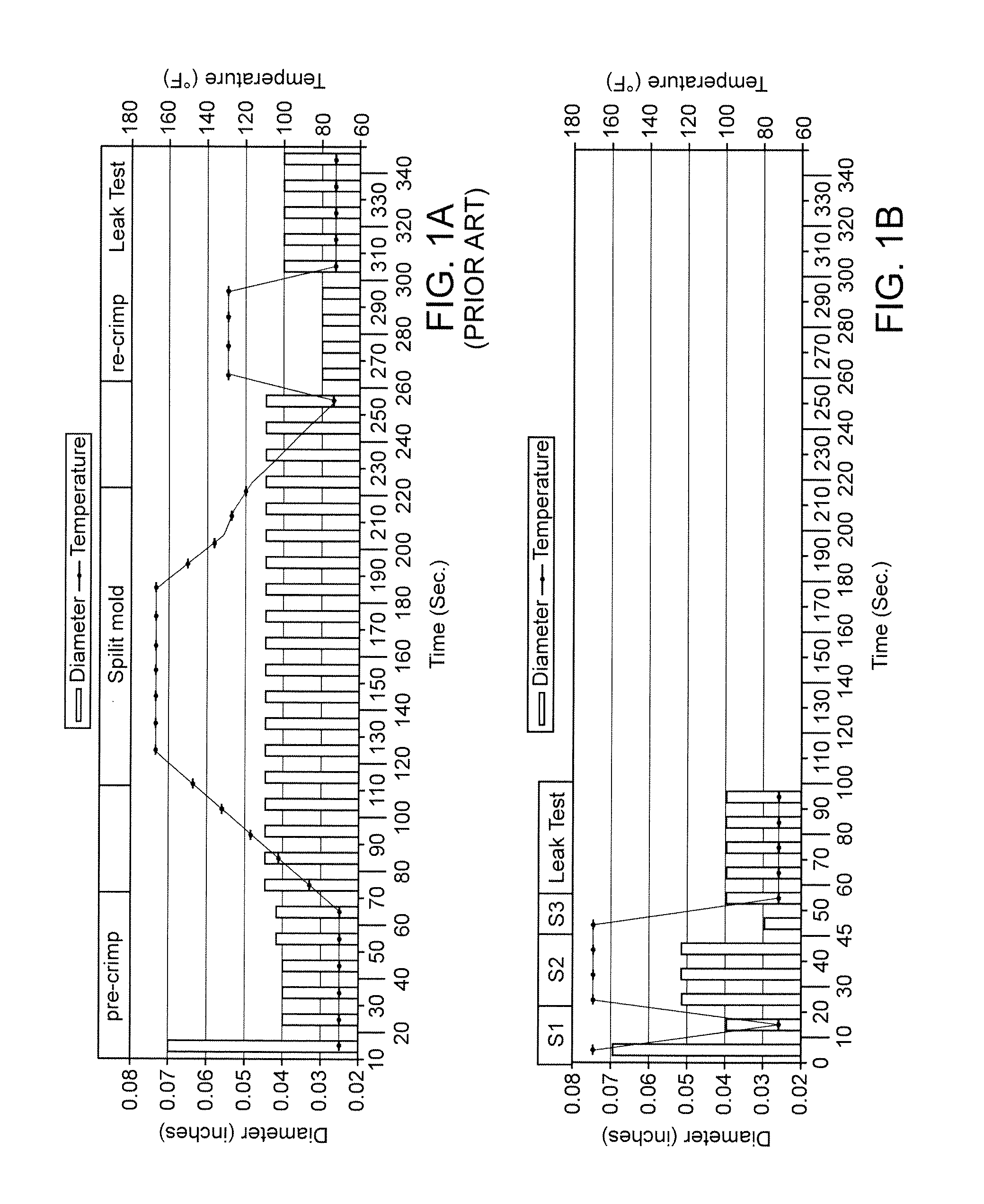
[0031]A stent having a pattern as described in U.S. Pat. Nos. 6,312,459 or 179,867 may have a starting, or manufactured outer surface diameter of 0.07 in. The stent is made from a metal or metal alloy. The stent may be crimped to a non-compliant balloon made from PEBAX material. When deployed the stent has a nominal 3 mm (0.118 in) outer diameter and 18 mm (0.708 in) length. For purposes of this disclosure, this stent will be referr...


PUM

PropertyMeasurementUnit
pressureaaaaaaaaaa
temperatureaaaaaaaaaa

Abstract

A process for crimping stents includes a multi-stage process producing a desired stent retention and crimped profile in a reduced amount of time. The process achieves results by utilizing particular combinations of heat and pressure during the crimping process, which was found to produce the desired results.

Description

BACKGROUND OF THE INVENTION[0001]1. Field of the Invention[0002]The present invention relates to drug-eluting medical devices; more particularly, this invention relates to processes for crimping a stent to a delivery balloon.[0003]2. Background of the Invention[0004]A known stent retention process consists of three operations, stent crimp, split mold and stent press. Stent crimp is the process by which the stent is placed on the catheter. First the stent is placed on a pre-crimp mandrel and placed in the crimp machine. The crimp machine closes onto the stent applying radial force causing the scent's diameter to be reduced to that of the pre-crimp mandrel. The pre-crimp mandrel diameter is selected based on the delivery systems folded balloon profile. After pre-crimp, the stent is removed from the mandrel and placed on a balloon delivery system, balloon catheter, or delivery system. The balloon catheter is placed into the crimp machine and radial force applied to reduce the diameter ...

Claims


Application Information

Patent Timeline
Patent Type & Authority Patents(United States)
IPC IPC(8): B23P11/00
CPCA61F2/958A61F2/95A61F2002/9522Y10T29/53952Y10T29/49927A61F2/9522A61F2/9524A61F2/9526
Inventor KNOTT, BOYD V.KADAKIA, SAMITORTEGA, LEOPOLDO
Owner ABBOTT CARDIOVASCULAR
Why Eureka
Try Eureka