Spacer for retaining cladding element on structural building element

a technology for retaining cladding and structural building elements, which is applied in the direction of building repairs, roof tools, roofing, etc., can solve the problems of poor thermal insulation properties of the assembly and defeat the purpose of providing insulation materials, and achieves the goal of achieving highly precise dimensions relatively easily, simple structure, and low tooling and extrusion costs

Active Publication Date: 2014-03-06
TECHNOFORM HLDG
View PDF7 Cites 2 Cited by
  • Summary
  • Abstract
  • Description
  • Claims
  • Application Information

AI Technical Summary

Benefits of technology

[0018]Spacers according to certain embodiments of the present teachings may be manufactured by extrusion as continuous profiles due their constant cross sections. Because such spacers have a relatively simple structure, the tooling costs and the extrusion costs will be relatively low while still permitting highly precise dimensions to be achieved relatively easily.
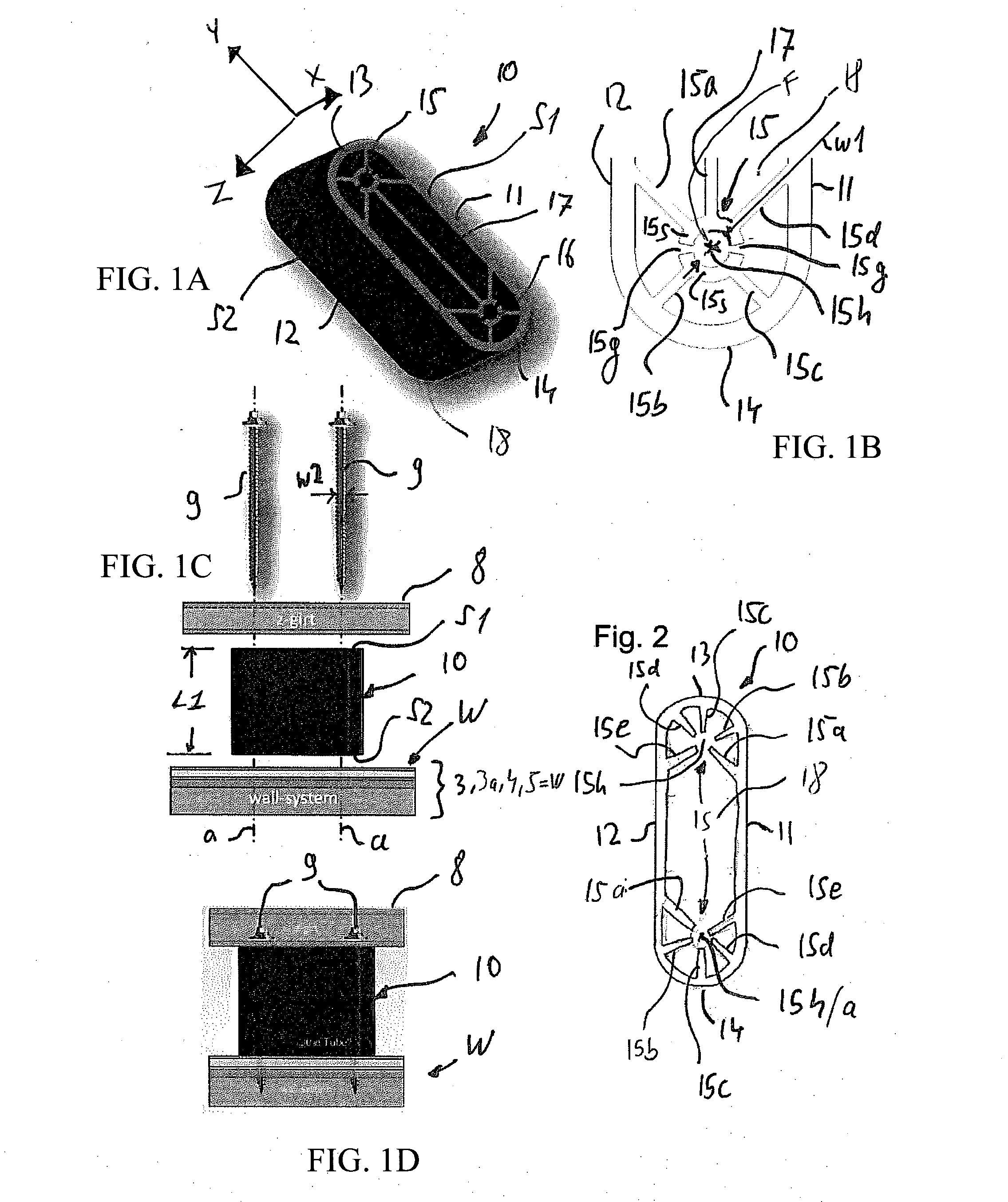
[0019]In addition or in the alternative, a spacer according to the present teachings may include one or more fastener holding devices formed by extension walls, protrusion ribs or the like. Such fastener holding devices enable a cladding element such as a Z-girt to be pre-attached or pre-mounted in a captive manner by simply inserting the fastener, such as a screw, into a fastener insertion path defined by the fastener holding device. In this case, the spacer, the fastener and the cladding element become a single, integral unit (in the form of a captive assembly) which can be easily handled by the person(s) who will mount or attach the captive assembly onto the building structure or element.

Problems solved by technology

Therefore, the thermal insulation properties of the assembly are poor, because the steel spacer 70 acts as a heat conductor through the insulating material IS, thereby defeating the purpose of providing the insulation material.

Method used


Image

  • Spacer for retaining cladding element on structural building element
  • Spacer for retaining cladding element on structural building element
  • Spacer for retaining cladding element on structural building element

Examples


first embodiment

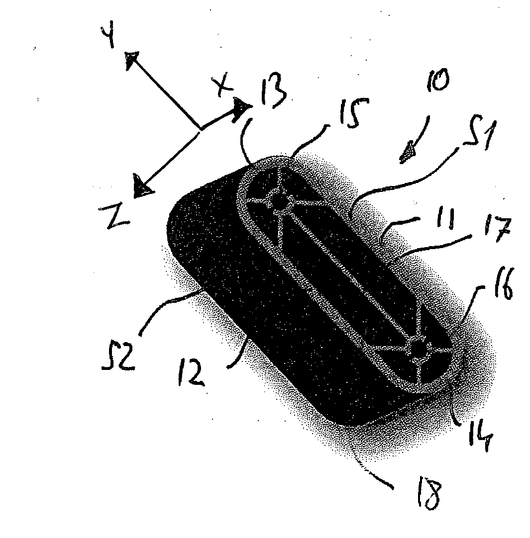
[0035]FIGS. 1A and 1B show the spacer according to the present teachings and FIGS. 1C and 1D show the spacer during a mounting operation and at the conclusion thereof, respectively.

[0036]The embodiment shown in FIG. 1 can be characterized, e.g., as having a tube-like structure, in the sense that it has an at least substantially hollow interior structure with a continuous enclosing (surrounding) wall, preferably a single continuous enclosing (surrounding) exterior wall. However, while the term “tube” is normally associated with hollow cylindrical structures, as used herein, the term “tube-like” is intended to encompass a broader range of substantially hollow structures.

[0037]For example, in the present embodiment, the enclosing wall of the spacer has a substantially rectangular cross-section with rounded or curved corners / ends, e.g., a rectangular oval, which is similar in shape to a horse racing track. But, the present teachings are not particularly limited in this regard and altern...

third embodiment

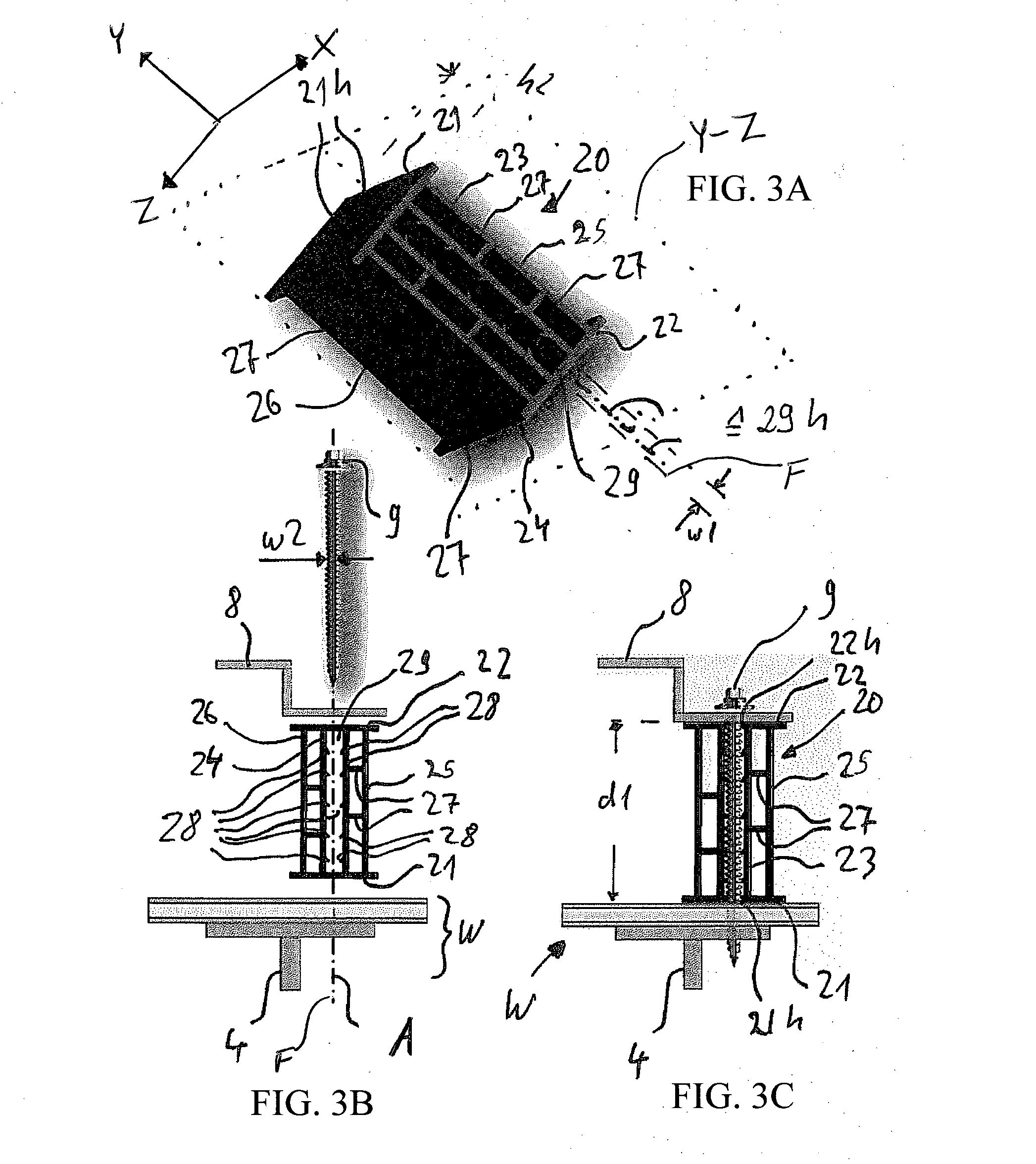
[0068]The third embodiment shown in FIG. 3 includes a second set of two parallel side walls 25, 26, which are also parallel to the first set of side walls 23, 24. However, the second set of side walls 25, 26 are optional and the person of ordinary skill in the art can readily determine whether to include the second set of side walls 25, 26 in view of the loads to be carried or supported by the spacer 20 in the actual application.

[0069]In the embodiment shown in FIG. 3, the side wall 25 is disposed parallel to the side wall 23 on the side thereof opposite to the interior space 29 and is connected to the side wall 23 by two connection walls 27, which are parallel to the flange walls 21, 22 (perpendicular to the side walls 23, 25). The same applies to the other side wall 26, which is parallel to the side wall 24 and is disposed on the side thereof that is opposite to the interior space 29. The side wall 26 is also connected to the side wall 24 by two connection walls 27 that extend par...

second embodiment

[0077]However, the direction of the extrusion of the block-like embodiment does not correspond to the direction F of the fastener insertion path 29h. Instead, the extrusion direction is perpendicular to the fastener insertion path 29h. Accordingly, the spacer 20 can also be produced in an endless manner, cut into elongated bars having a length, for example, of 6 m for shipment to the customer, and then cut into shorter segments of a predetermined height h2. However, unlike in the first and second embodiment, this height h2 does not determine the spacing distance d1 between the wall structure W and the cladding element 8; rather, the height h2 determines the areas of contact with the wall structure W and the cladding element 8, respectively.

[0078]Thus, this third embodiment enables the contact area to be variable by cutting the bars into different lengths h2. However, the spacing distance d1 is not variable. On the other hand, in the first and second embodiments, the spacing distance...


PUM


Abstract

A spacer for retaining a cladding element on a building element in a spaced apart relationship has a constant cross-section in its longitudinal direction. The spacer is an at least substantially hollow structure having at least one external wall enclosing an interior space. At least one fastener insertion path extends through the interior space. The fastener insertion path is capable of holding a fastener disposed therein prior to mounting the spacer and cladding element on the building element. The spacer preferably comprises planar surfaces on opposite sides thereof that are configured to abut the cladding element and the building element, respectively.

Description

CROSS-REFERENCE[0001]This application claims priority to U.S. provisional application No. 61 / 695,280 filed on Aug. 30, 2012, the contents of which are fully incorporated herein.TECHNICAL FIELD[0002]The present invention generally relates to a spacer for retaining a cladding element (component) in a spaced relationship relative to a structural building element (component).BACKGROUND ART[0003]In the construction of buildings, cladding elements such as girts, purlins, panels, roof elements, rain walls etc. are often attached to structural building elements such as walls, roofs or other supporting elements such as pillars, studs, etc.[0004]Such a known wall or roof arrangement (assembly) is shown in FIG. 4, which corresponds to FIG. 1 of CA 2 763 058 A1.[0005]In FIG. 4 the wall assembly includes an inner wall panel 2 held in a spaced apart relationship to an outer wall panel3 by a metal stud 4, thereby forming an interior space 5. The outer wall 3 is covered by an exterior wall cover 3a...

Claims


Application Information

Patent Timeline
Patent Type & Authority Applications(United States)
IPC IPC(8): E04F13/08
CPCE04F13/0835E04F13/0805E04F13/0857Y10T403/7141
Inventor MOSES, DIRKOSSADNIK, SEBASTIANORTH, THOMASMARANDITSCH, VIKTORBEBBER, FERDINANDPOEHLMANN, THORSTENHUBRICH, BJORN
Owner TECHNOFORM HLDG
Why Eureka
Try Eureka