
Collision-avoidance system for ground crew using sensors

a technology of collision avoidance and ground crew, which is applied in the direction of instruments, measurement devices, aircraft traffic control, etc., can solve the problems that the wing tips or tails of the towed aircraft may inadvertently collide with the ground obstacle, and the flight crew members of the aircraft attempting to maneuver the aircraft on the ground may have difficulty in being aware,

Active Publication Date: 2014-03-06
HONEYWELL INT INC
View PDF13 Cites 42 Cited by
  • Summary
  • Abstract
  • Description
  • Claims
  • Application Information

AI Technical Summary

Benefits of technology

This patent describes a system that helps avoid collisions between an aircraft and ground obstacles. It uses radar sensors on the surface of the aircraft to detect the reflections of radar signals from ground objects. The system then sends the information about the detected objects to a processing system, which calculates the distance between the aircraft and each object. The system also displays a virtual representation of the objects on a screen, allowing the pilot or ground crew to see where the objects are located and take appropriate action to avoid a collision. Overall, this system helps increase safety and prevent accidents.

Problems solved by technology

Aircraft flight crew members or ground crew members maneuvering an aircraft on the ground may have difficulty in being aware of potential collisions of portions of the aircraft with other objects as the aircraft is moving.
The difficulty arises, in part due to limited visibility caused by the relatively large size of the aircraft and or the tow tug, and due to potential distractions, such as other moving vehicles, or such as other taxi way maneuvers and related operations being performed by the aircraft crew.
If a land-based ground obstacle is in the way of the towed aircraft, the wing tips or tail of the towed aircraft may inadvertently collide with the ground obstacle.

Method used


Image

  • Collision-avoidance system for ground crew using sensors
  • Collision-avoidance system for ground crew using sensors
  • Collision-avoidance system for ground crew using sensors

Examples


Embodiment Construction

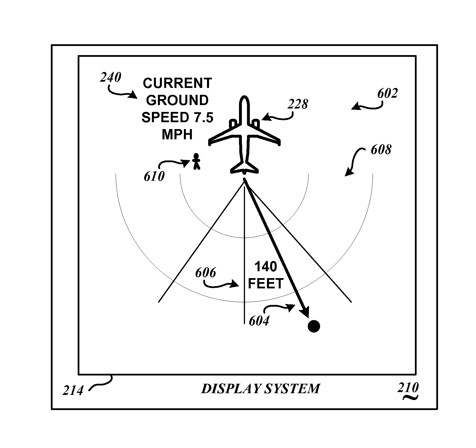
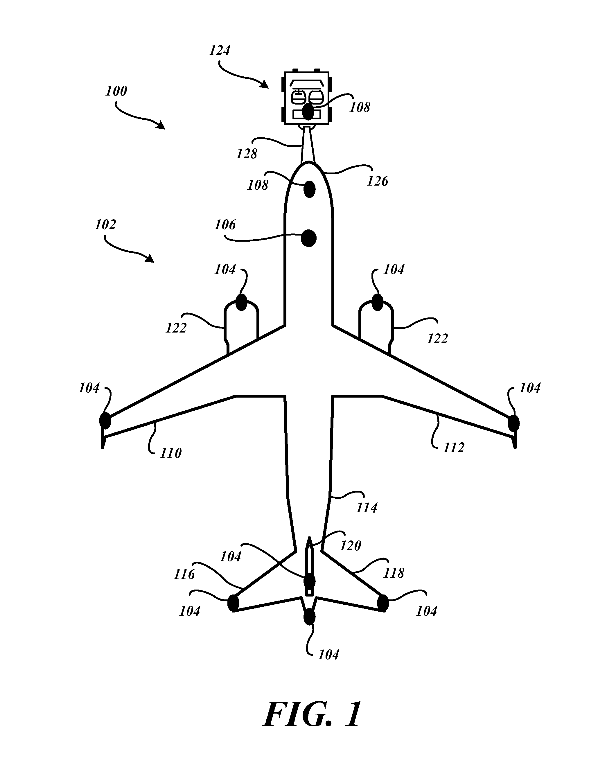
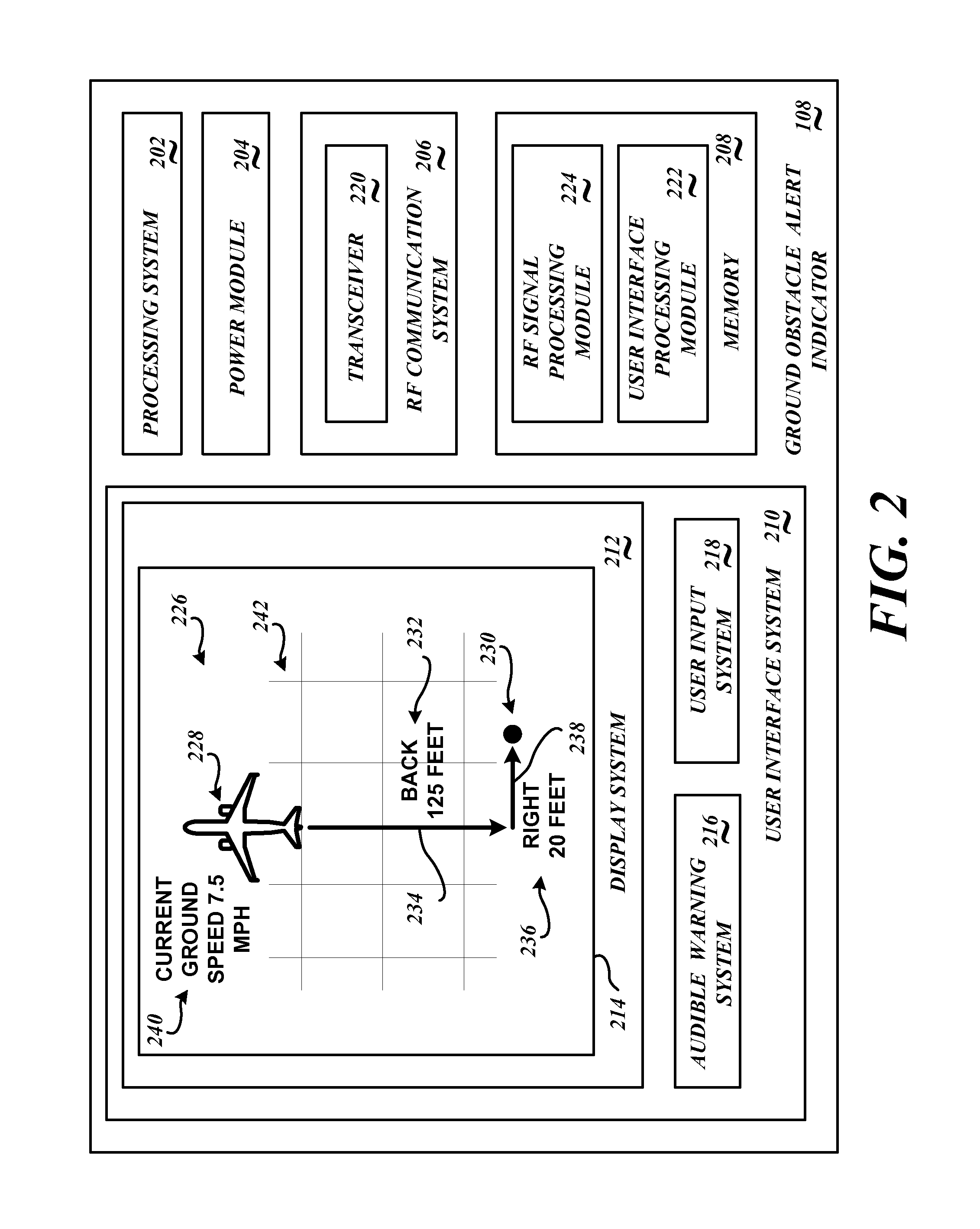
[0013]FIG. 1 is a view of an embodiment of an exemplary ground obstacle collision-avoidance system 100 embodied in an installation aircraft 102 (interchangeably referred to as the aircraft 102). The ground obstacle collision-avoidance system 100 includes radar sensor modules 104 (e.g., a radar emitter / detector device) located on the exterior of the aircraft 102 at selected locations that may be at risk for collision with a ground obstacle while the aircraft 102 is being moved under the control of the aircraft crew and / or being towed by a ground crew.

[0014]The radar sensor modules 104 emit radar signals. If a radar signal return from a ground obstacle is detected by one or more of the radar sensor modules 104, a determination is made of the location of the detected ground obstacle. During movement of the aircraft 102 while under the control of the aircraft crew and / or during the towing of the aircraft 102 by the ground crew, a presented plan view will indicate the existence and the r...


PUM


Abstract

A ground obstacle collision-avoidance system includes a plurality of radar sensor modules that each receive at a radar detector radar return signals corresponding to reflections of the emitted signal from a ground obstacle, and transmits radar information associated with the received radar signal reflections reflected from the ground obstacle, wherein each of the plurality of radar sensor modules are uniquely located on a surface of an aircraft that is at risk for collision with a ground obstacle if the aircraft is moving; a gateway unit that receives the radar information transmitted from the radar sensor module and transmits information associated with the received radar information; a processing system configured to determine a distance from the installation aircraft to a detected ground object detected; and a display configured to present a plan view indicating an aircraft icon and a graphical ground obstacle icon that is associated with the detected ground obstacle.

Description

PRIORITY CLAIM[0001]This application claims the benefit of U.S. Provisional Application Ser. No. 61 / 653,297, filed May 30, 2012, the contents of which are hereby incorporated by reference in their entirety. This application further claims the benefit of U.S. Provisional Application Ser. No. 61 / 706,632, filed Sep. 27, 2012, the contents of which are hereby incorporated by reference in their entirety.BACKGROUND OF THE INVENTION[0002]Aircraft flight crew members or ground crew members maneuvering an aircraft on the ground may have difficulty in being aware of potential collisions of portions of the aircraft with other objects as the aircraft is moving. The difficulty arises, in part due to limited visibility caused by the relatively large size of the aircraft and or the tow tug, and due to potential distractions, such as other moving vehicles, or such as other taxi way maneuvers and related operations being performed by the aircraft crew.[0003]If a land-based ground obstacle is in the ...

Claims


Application Information

Patent Timeline
Patent Type & Authority Applications(United States)
IPC IPC(8): G01S13/93G01S13/933G01S13/931G01S13/934
CPCG01S13/9303G01S7/003G01S13/93G08G5/04G08G5/065G01S2013/916G08G5/0021G01S7/04G01S13/931G01S7/22G01S13/934G01S13/933
Inventor LAMKIN, ANDREW FANNONSTARR, JEFFREY W.BUSTER, DUKE
Owner HONEYWELL INT INC
Learn More