System and method for utilizing multiple sensors

a technology of sensors and sensors, applied in the field of systems and methods for utilizing multiple sensors, can solve the problems of significantly less information available from the current airborne sensor system, limited three-dimensional feature extraction,

Active Publication Date: 2014-03-06
GE AVIATION SYST LLC
View PDF2 Cites 3 Cited by
  • Summary
  • Abstract
  • Description
  • Claims
  • Application Information

AI Technical Summary

Problems solved by technology

Contemporary airborne sensor systems are limited in three-dimensional feature extraction due to the proximity of the camera systems as the current camera systems require a great reduction in imaging noise to be able to extract dimensional artifacts from the image set.
The precision of information available from these systems is significantly less than desired.

Method used


Image

  • System and method for utilizing multiple sensors
  • System and method for utilizing multiple sensors
  • System and method for utilizing multiple sensors

Examples


Embodiment Construction

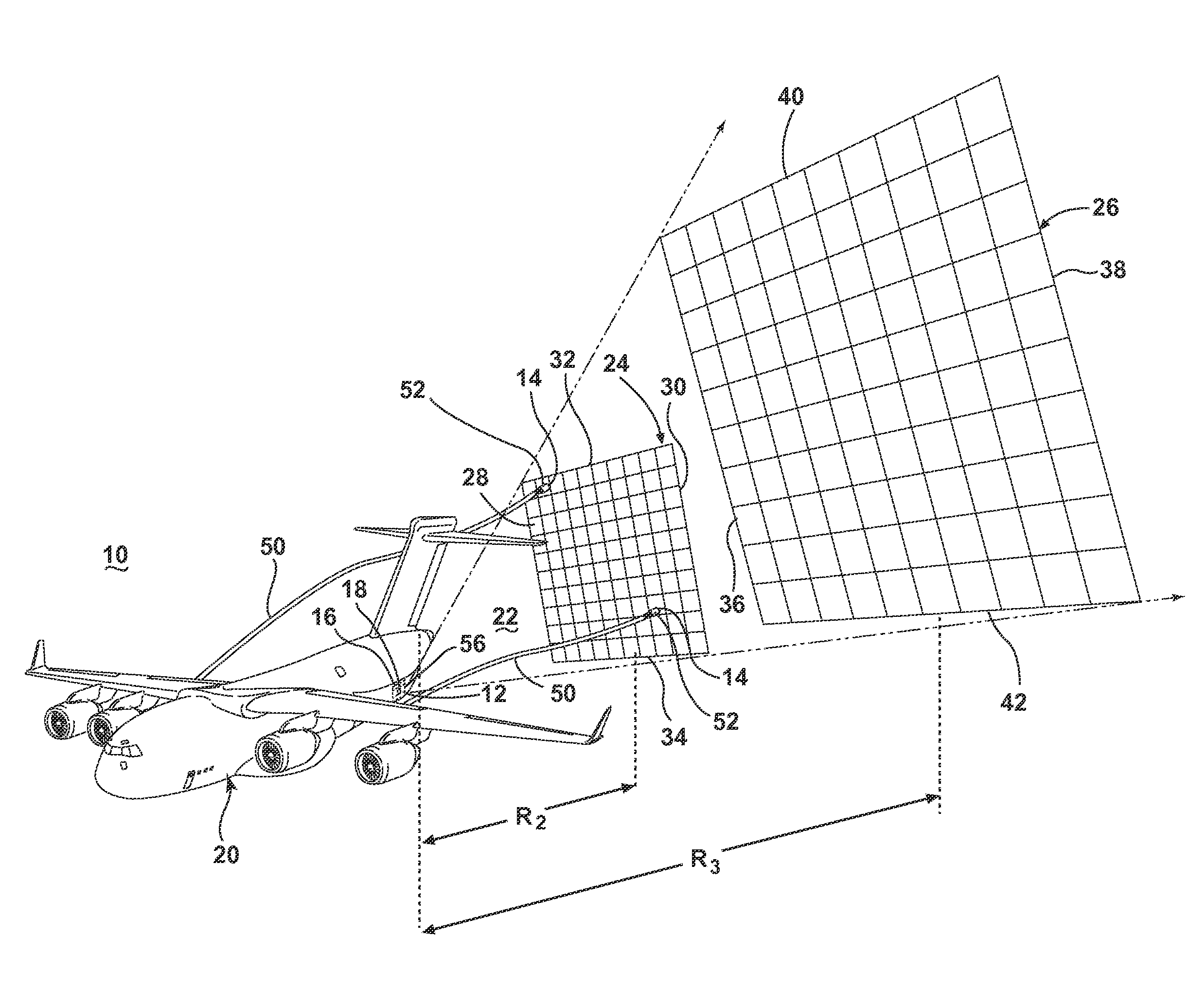
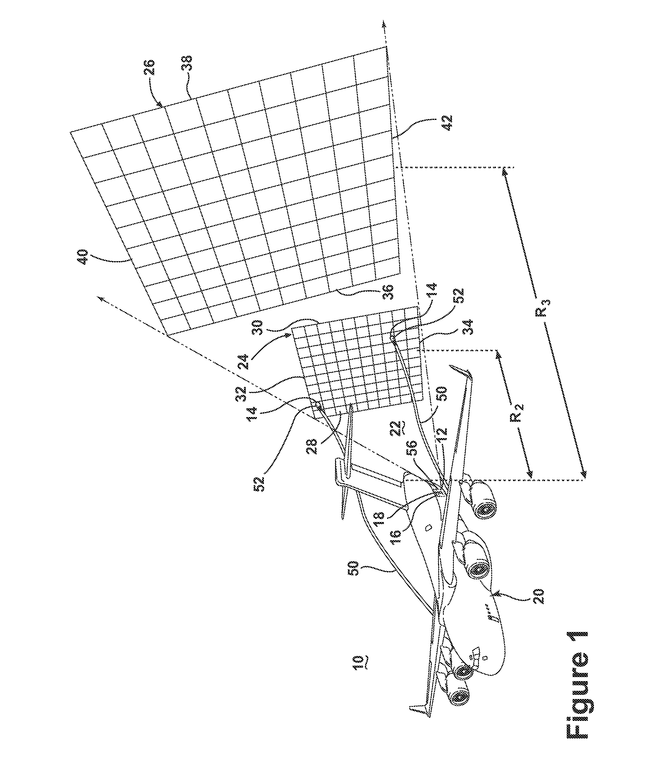
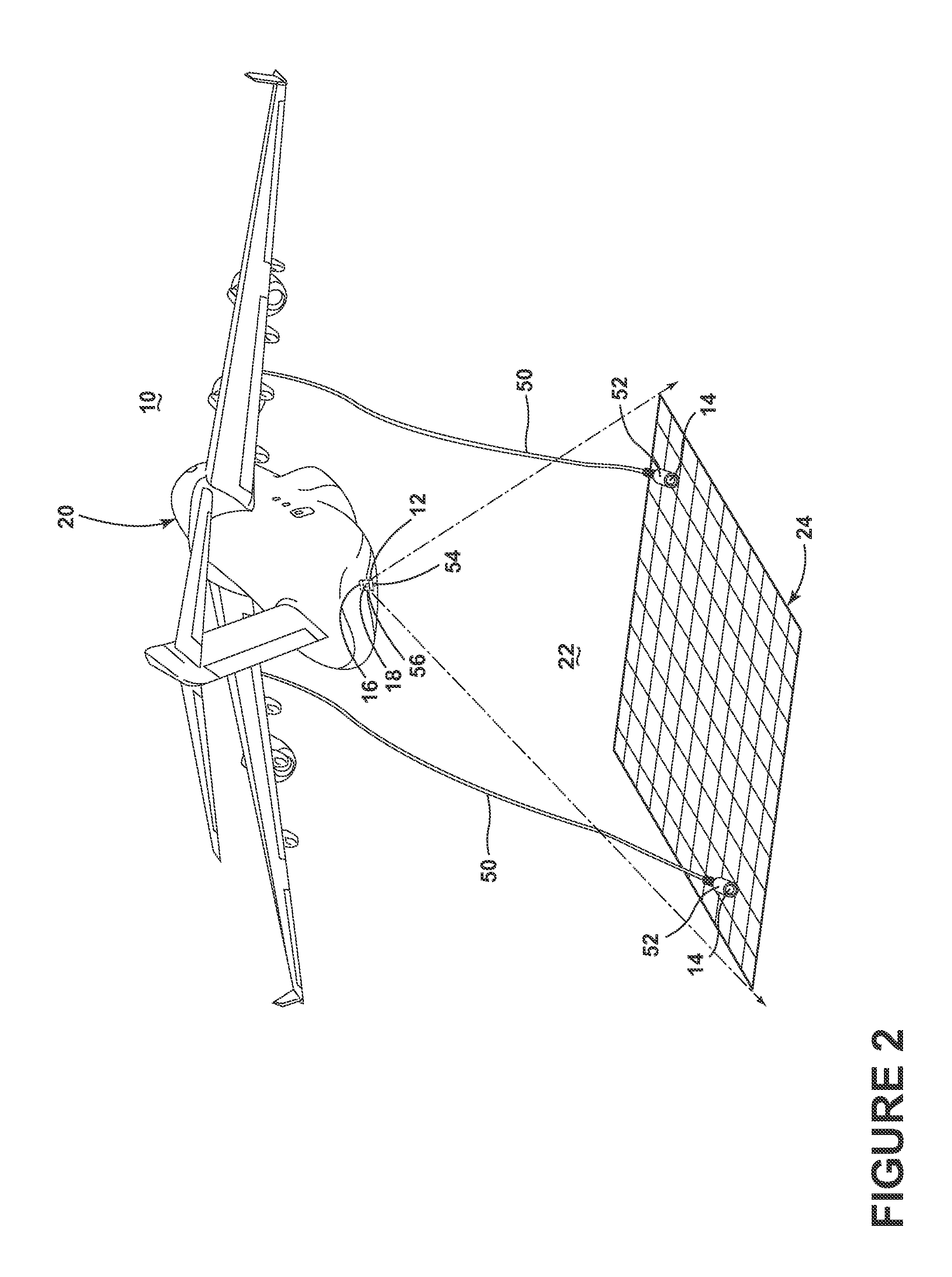
[0008]The embodiments of the present invention are related to a sensor system and methods of utilizing multiple airborne sensors. FIG. 1 illustrates an embodiment of the sensor system 10, which has been illustrated as including a grid generator 12, multiple sensors 14, a position detector 16, and a coordination engine 18 operably coupled with an aircraft 20. More specifically, the aircraft 20 may be equipped with a grid generator 12, which may project a relative navigation grid, such as a plurality of intersecting lines, into space within a field of transmission 22. The general details of how to project the relative navigation grid are known in the art, which include the disclosure in U.S. Pat. No. 7,681,839, issued Mar. 23, 2010, entitled Optical Tracking System For Refueling, and US 2011 / 0153205, published Jun. 23, 2011, entitled Relative Navigation System, both of which are incorporated by reference. Therefore, the specific details of the grid generation will not be fully describ...


PUM


Abstract

A sensor system having multiple sensors and having a grid generator projecting into space a relative navigation grid and a method of utilizing multiple airborne sensors operably coupled to an aircraft and coordinating the sensor outputs from the airborne sensors based on the determined spatial position of the multiple sensors and a method for utilizing multiple airborne sensors.

Description

BACKGROUND OF THE INVENTION[0001]Airborne sensor systems may be used to obtain data and information, such as three dimensional images and topography. Such systems may collect time-synchronous data or images and the individual data elements, such as images, may then be pieced together and coupled to a position and orientation system to transform 2-D data to 3-D data and / or improve the quality of the 3-D date. Contemporary airborne sensor systems are limited in three-dimensional feature extraction due to the proximity of the camera systems as the current camera systems require a great reduction in imaging noise to be able to extract dimensional artifacts from the image set. Separation of the camera systems provides for a reduction in image quality while maintaining the capability of the system. The precision of information available from these systems is significantly less than desired.BRIEF DESCRIPTION OF THE INVENTION[0002]In one embodiment, the invention relates to a sensor system ...

Claims


Application Information

Patent Timeline
Patent Type & Authority Applications(United States)
IPC IPC(8): G01C23/00G01S17/89
CPCB64D39/00G01S17/89G01S5/0226G01S5/16G01S17/88G01C11/02
Inventor BUEHLER, ERIC DANIELMCCAULEY, DAVID KEVIN
Owner GE AVIATION SYST LLC
Why Eureka
Try Eureka