
Non-intrusive exhaust gas sensor monitoring based on fuel vapor purge operaton

Active Publication Date: 2014-03-06
FORD GLOBAL TECH LLC
View PDF6 Cites 16 Cited by
  • Summary
  • Abstract
  • Description
  • Claims
  • Application Information

AI Technical Summary

Benefits of technology

The patent text describes a method for monitoring the health of exhaust gas sensors in an engine by adjusting engine operation based on sensor degradation. By compensating for sensor degradation based on vapor purge operation, the likelihood of sensor misdiagnosis is reduced, and sensor diagnostics can be performed over a wider range of engine operating conditions. The method uses data collected during DFSO and is non-intrusive. By determining degradation of an exhaust gas sensor based on a line length and time delay, the accuracy of sensor degradation determination is improved. Additionally, adjusting engine operation responsive to exhaust gas sensor degradation can improve combustion operation and decrease emissions.

Problems solved by technology

Degradation of an exhaust gas sensor may cause engine control degradation that may result in increased emissions and / or reduced vehicle drivability.
However, vapor purge operation may negatively affect exhaust gas degradation monitoring during DFSO.
For example, if vapor purging operation is implemented in the engine during sensor monitoring, the exhaust gas sensor may be incorrectly diagnosed.
However, this may limit window for sensor diagnostics and as a result decrease the number diagnostic operations performed.
Consequently, combustion operation may be degraded when a degraded sensor is not diagnosed in a desired time period.

Method used


Image

  • Non-intrusive exhaust gas sensor monitoring based on fuel vapor purge operaton
  • Non-intrusive exhaust gas sensor monitoring based on fuel vapor purge operaton
  • Non-intrusive exhaust gas sensor monitoring based on fuel vapor purge operaton

Examples


Embodiment Construction

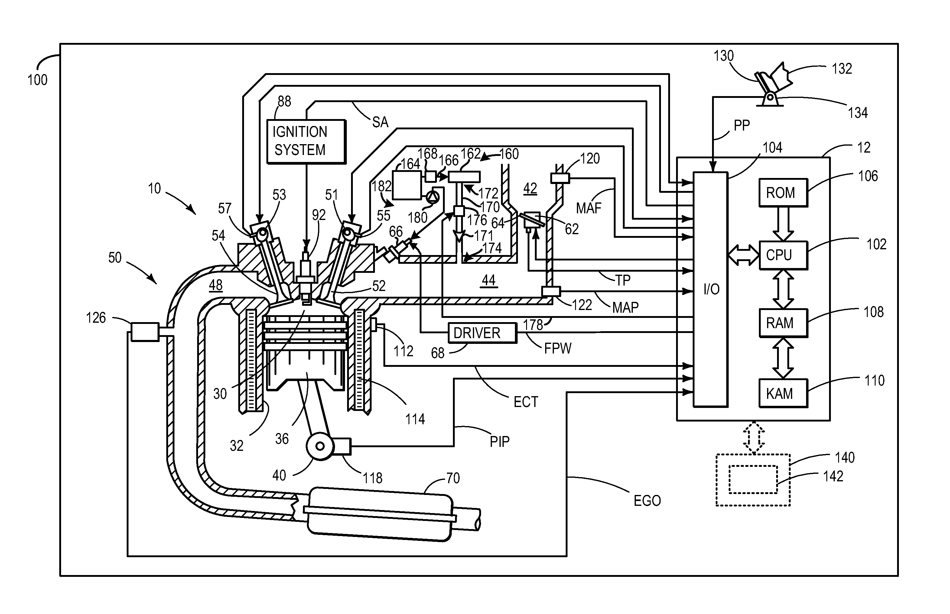
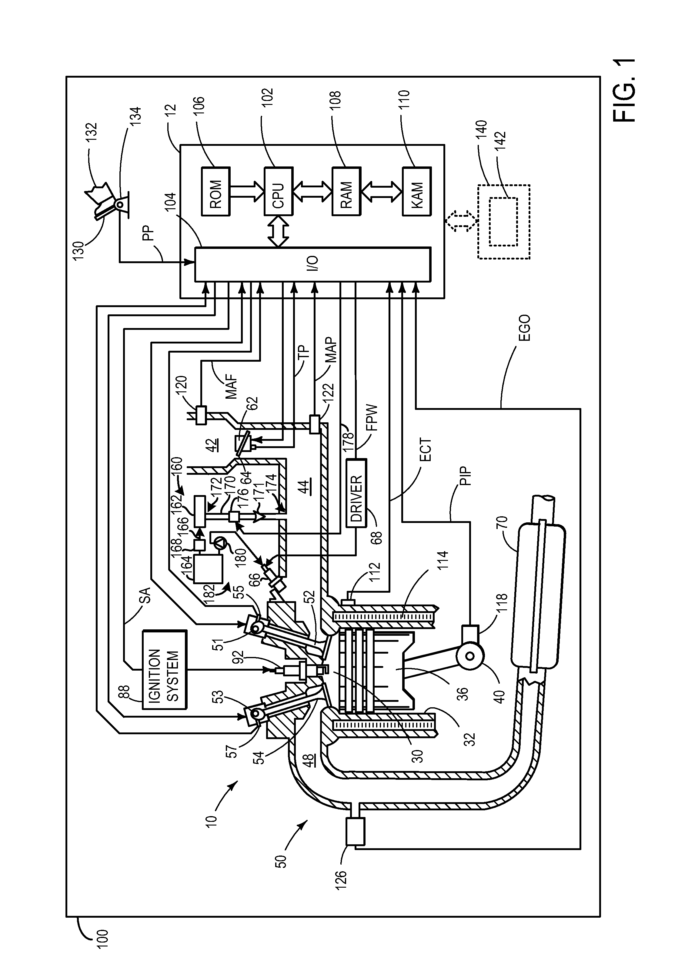
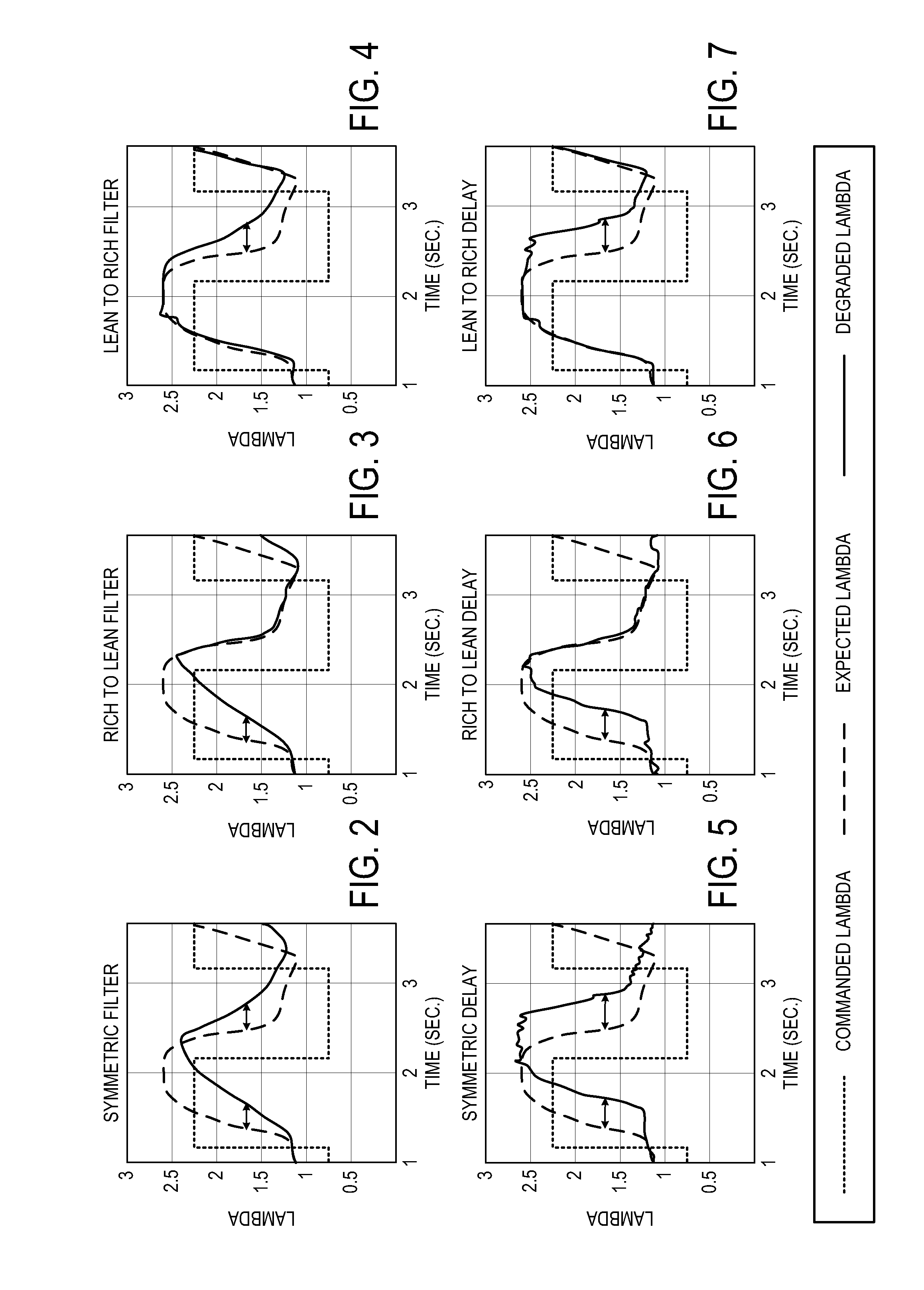
[0022]The following description relates to an approach for determining degradation of an exhaust gas sensor. More particularly, the systems and methods described below may be implemented to determine exhaust gas sensor degradation during a deceleration fuel shut-off (DFSO) transition based on vapor purge operation in the engine. Specifically, if it is determined the fuel vapor purge operation is occurring during exhaust gas sensor monitoring a compensation factor may be applied to a diagnostic algorithm to account for the change in air fuel ratio caused by the purge operation. In this way, a robust diagnostic algorithm may be unobtrusively employed during DFSO and the likelihood of misdiagnosis of the exhaust gas sensor caused by fuel vapor purge operation is greatly reduced.

[0023]FIG. 1 shows an engine including an exhaust gas sensor. FIGS. 2-7 show expected and degraded lambda for each of the six degradation behaviors of the exhaust gas sensor including a response with an air-fuel...


PUM


Abstract

A method of monitoring an exhaust gas sensor coupled in an engine exhaust in an engine is provided. The method includes adjusting engine operation responsive to exhaust gas sensor degradation, the degradation identified during deceleration fuel shut-off (DFSO) and compensated based on whether vapor purge operation is occurring in the engine during DFSO.

Description

FIELD[0001]The present disclosure relates to an exhaust gas sensor in a motor vehicle and method for monitoring the exhaust gas sensor.BACKGROUND AND SUMMARY[0002]An exhaust gas sensor may be positioned in an exhaust system of a vehicle to detect an air / fuel ratio of exhaust gas exhausted from an internal combustion engine of the vehicle. The exhaust gas sensor readings may be used to control operation of the internal combustion engine to propel the vehicle.[0003]Degradation of an exhaust gas sensor may cause engine control degradation that may result in increased emissions and / or reduced vehicle drivability. In particular, an exhaust gas sensor may exhibit six discrete types of degradation behavior. The degradation behavior types may be categorized as asymmetric type degradation (e.g., rich-to-lean asymmetric delay, lean-to-rich asymmetric delay, etc.) that affects only lean-to-rich or rich-to-lean exhaust gas sensor response rates, or symmetric type degradation (e.g., symmetric de...

Claims


Application Information

Patent Timeline
IPC IPC(8): F01N11/00F02D41/34F02D41/26
CPCF02D41/123F02D41/1495F02D41/003F02D41/0035F01N11/007Y02T10/40F02D41/1454F02D41/1486
Inventor BANKER, ADAM NATHANULRICH, MICHAEL JAMESMAKKI, IMAD HASSANKERNS, JAMES MICHAEL
Owner FORD GLOBAL TECH LLC
Learn More