
Impedance compensation for operational amplifiers used in variable environments

a variable environment and amplifier technology, applied in the field of operational amplifiers, can solve the problems of over-exhaustion of electrical power dissipation, designers may not consider the effects of other ambient energy sources such as high-energy electromagnetic radiation, or other sources of ionizing radiation encountered in the presence, and achieve the effect of less impact on circuit performance, high stress within the circuit, and reduced electrical power dissipation

Active Publication Date: 2014-03-13
CRANE ELECTRONICS INC
View PDF2 Cites 10 Cited by
  • Summary
  • Abstract
  • Description
  • Claims
  • Application Information

AI Technical Summary

Benefits of technology

The patent text discusses how changes in environmental conditions, such as temperature, can affect the input offset voltage and bias current of an op-amp. This can be a problem when using the op-amp in extreme temperatures or varying environments. The patent aims to address this issue and provide a solution to control or adjust the errors caused by environmental conditions.

Problems solved by technology

However, this approach can cause unnecessarily high stresses within the circuit and can lead to an excessive amount of electrical power dissipation.
Other solutions that employ thermistors having an exaggerated temperature dependence to reduce temperature sensitivity fail to address radiation effects.
Nevertheless, designers may fail to consider effects from other ambient energy sources such as high-energy electromagnetic radiation, or other sources of ionizing radiation encountered in the presence of ionized particles.

Method used


Image

  • Impedance compensation for operational amplifiers used in variable environments
  • Impedance compensation for operational amplifiers used in variable environments
  • Impedance compensation for operational amplifiers used in variable environments

Examples


Embodiment Construction

[0025]In the following description, certain specific details are set forth in order to provide a thorough understanding of various disclosed embodiments. However, one skilled in the relevant art will recognize that embodiments may be practiced without one or more of these specific details, or with other methods, components, materials, etc. In other instances, well-known structures associated with operational amplifiers and associated circuits have not been shown or described in detail to avoid unnecessarily obscuring descriptions of the embodiments.

[0026]Unless the context requires otherwise, throughout the specification and claims which follow, the word “comprise” and variations thereof, such as, “comprises” and “comprising” are to be construed in an open, inclusive sense, that is as “including, but not limited to.”

[0027]Reference throughout this specification to “one embodiment” or “an embodiment” means that a particular feature, structure or characteristic described in connection...


PUM


Abstract

A dual compensation operational amplifier is suitable for use in an environment that experiences fluctuations in ambient energy levels. A dual compensation impedance can be determined to nullify or compensate for effects of an input offset voltage or an input bias current or both. Adjustments to the dual compensation impedance can be made based on calibration data for various environmental conditions so that the dual compensation impedance can be either pre-set for anticipated conditions in different target operational environments, or automatically adjusted in-situ. Target operational environments that may benefit from such a dual compensation impedance include remote areas that experience extreme or variable temperatures, high altitudes, space, or high radiation environments.

Description

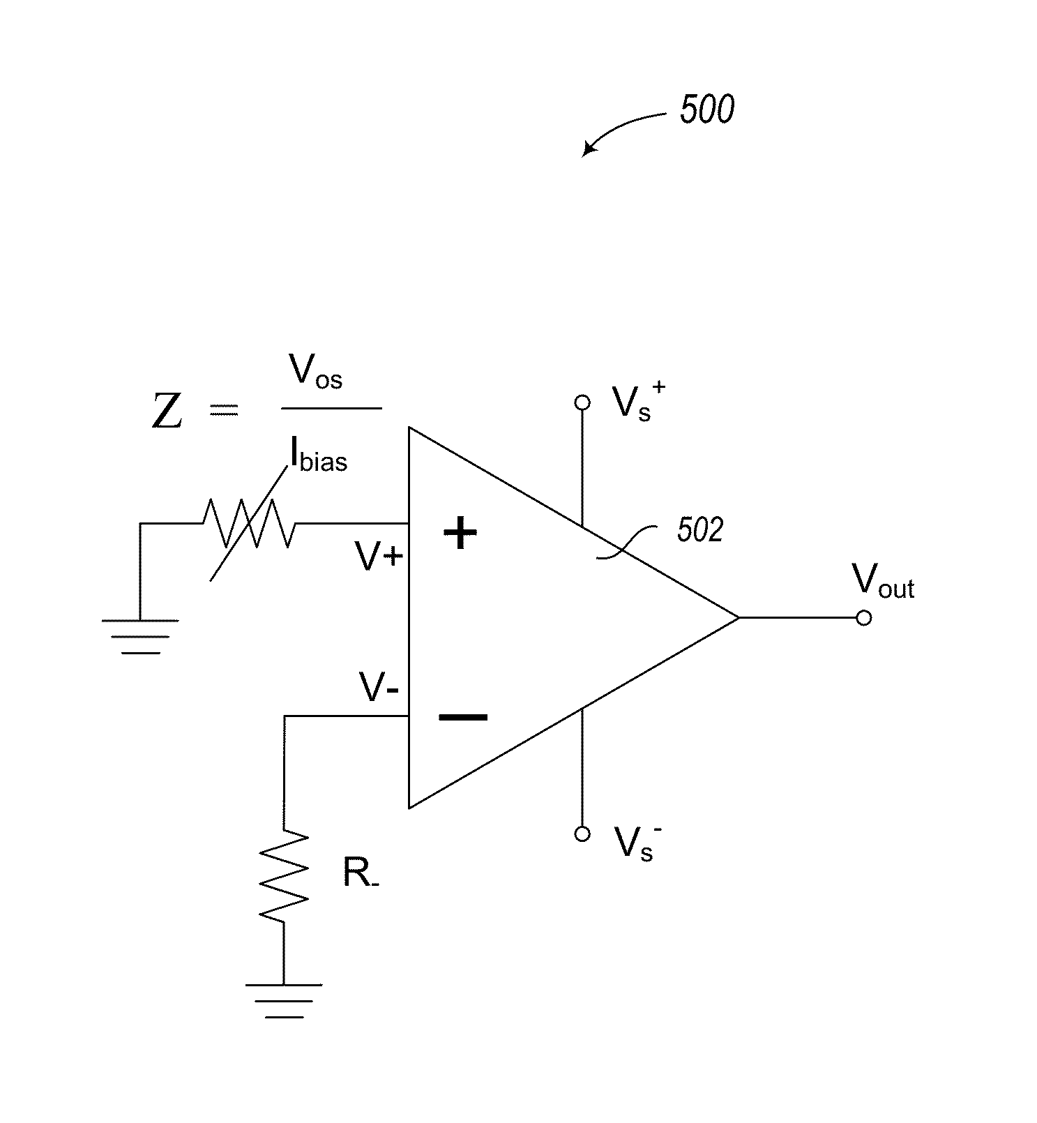
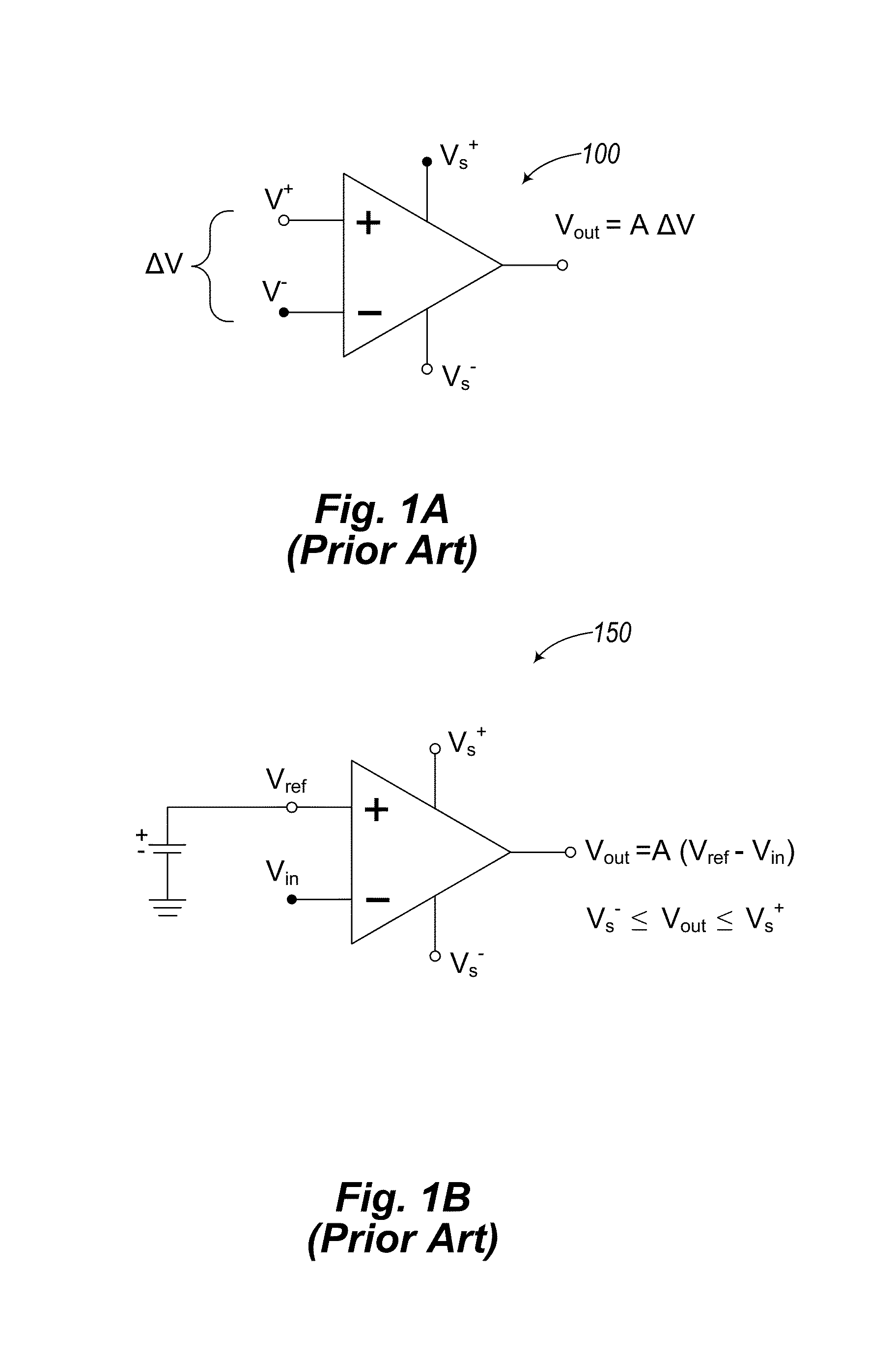
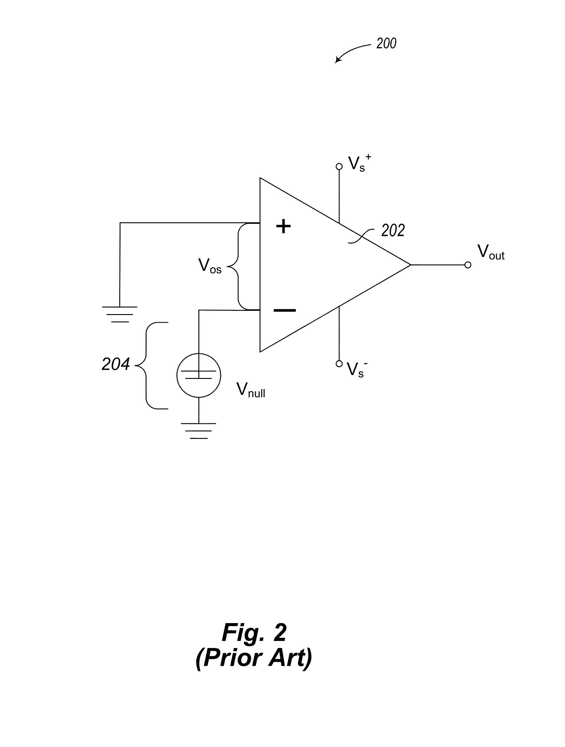
BACKGROUND[0001]1. Technical Field[0002]The present disclosure generally relates to operational amplifiers used in electrical and electronic circuitry and, in particular, to ways of adjusting operational amplifiers to compensate for variations in performance that arise in certain environments.[0003]2. Description of the Related Art[0004]Operational amplifiers (“op-amps”) are general purpose differential voltage amplifiers commonly used in electric circuits for many different applications. For example, op-amps are frequently used as building blocks in audio systems that involve complex signal processing circuitry to amplify sound. An idealized op-amp 100, shown in FIG. 1A, is a three-terminal device that has two input terminals, V+ (a non-inverting input), V− (an inverting input), and one output terminal, Vout. (Additional terminals are provided to connect a power source (e.g., battery) at Vs+ and Vs−). The differential input voltage to be amplified is ΔV =V+−V−. Components internal ...

Claims


Application Information

Patent Timeline
IPC IPC(8): H03F3/45
CPCH03F3/3069H03F3/4508H03F3/45475H03F3/45928H03F2203/45528H03F2203/45586H03F2203/45588H03F2203/45591H03F1/14H03F1/30H03F3/45
Inventor LAM, CUONKUEHNY, JAYPERCHLIK, DAVID
Owner CRANE ELECTRONICS INC
Learn More