Piezoelectric vibrating piece, piezoelectric vibrator, oscillator, electronic apparatus and radio timepiece

a piezoelectric and vibrating arm technology, applied in the field of piezoelectric vibrating pieces, piezoelectric vibrators, oscillators, electronic apparatuses and radio timepieces, can solve the problems of reducing the rigidity of the vibrating arm parts and losing the vibration balance, and achieves excellent reliability, suppressing the reduction of rigidity, and high-quality products.

Active Publication Date: 2014-03-20
SII CRYSTAL TECH
View PDF2 Cites 20 Cited by
  • Summary
  • Abstract
  • Description
  • Claims
  • Application Information

AI Technical Summary

Benefits of technology

The present invention provides a piezoelectric vibrating piece that can correct vibration imbalance while maintaining rigidity. By dividing the groove portion into two parts, it reduces stress concentration to the base end of the v UPPET vibrating arm and increases rigidity. This also reduces variation in weight caused by etching residue and assists in maintaining a balanced weight distribution along the vibrating arm. The groove widths of the second groove portion can be narrowed to further enhance rigidity. Using this piezoelectric vibrating piece in a piezoelectric vibrator, an electronic apparatus, or a radio timepiece, results in improved impact resistance, reliability, and durability of the products.

Problems solved by technology

That is, when the groove portions 212 are provided on the vibrating arm portions 210 and 211, there is also “a problem that the vibration balance is lost” due to the etching residue 213 in addition to the “problem that the rigidity of the vibrating arm portions is reduced”.

Method used


Image

  • Piezoelectric vibrating piece, piezoelectric vibrator, oscillator, electronic apparatus and radio timepiece
  • Piezoelectric vibrating piece, piezoelectric vibrator, oscillator, electronic apparatus and radio timepiece
  • Piezoelectric vibrating piece, piezoelectric vibrator, oscillator, electronic apparatus and radio timepiece

Examples


Embodiment Construction

[0040]Next, an embodiment of the present invention will be explained based on the drawings.

(Piezoelectric Vibrating Piece)

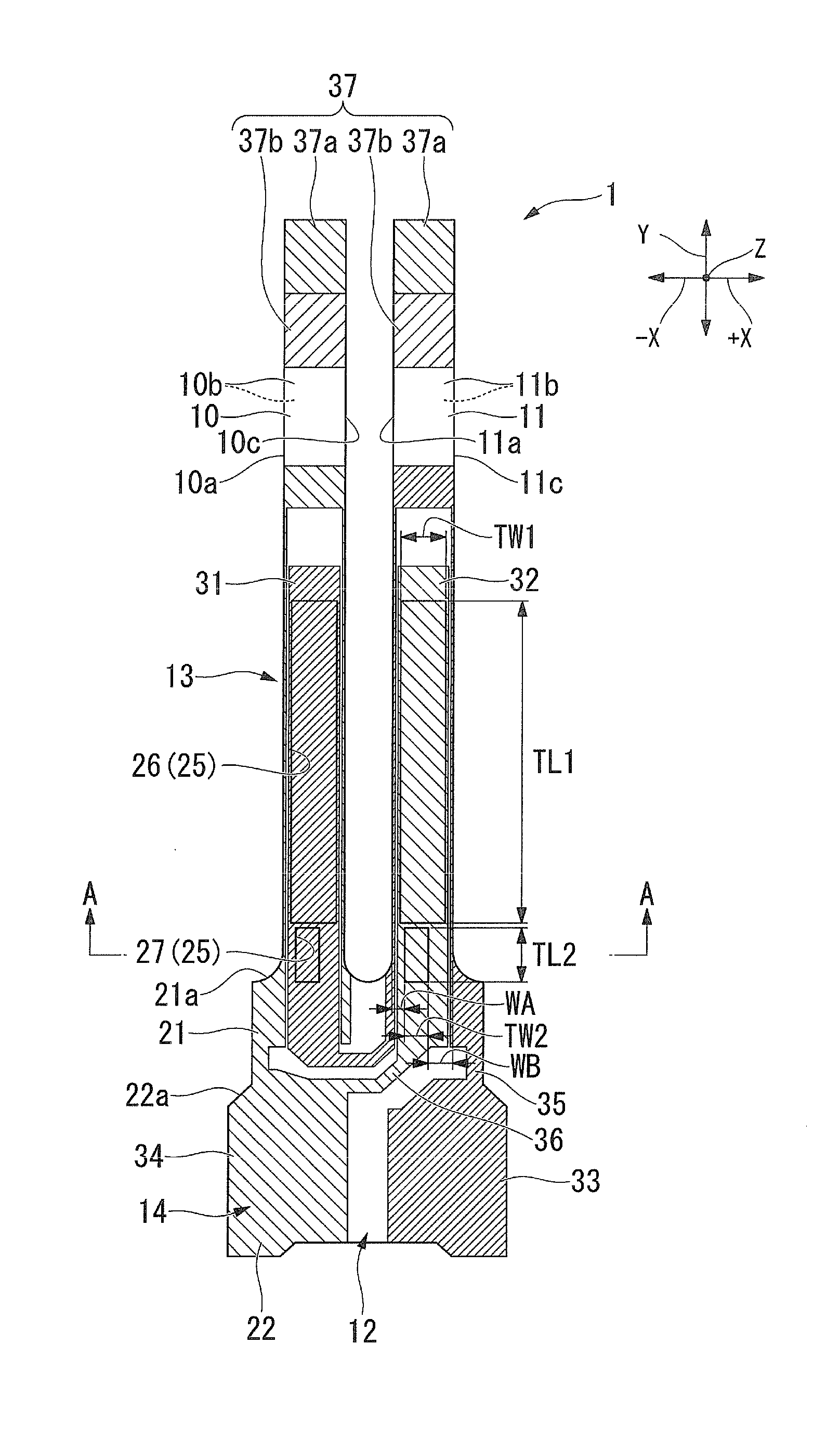
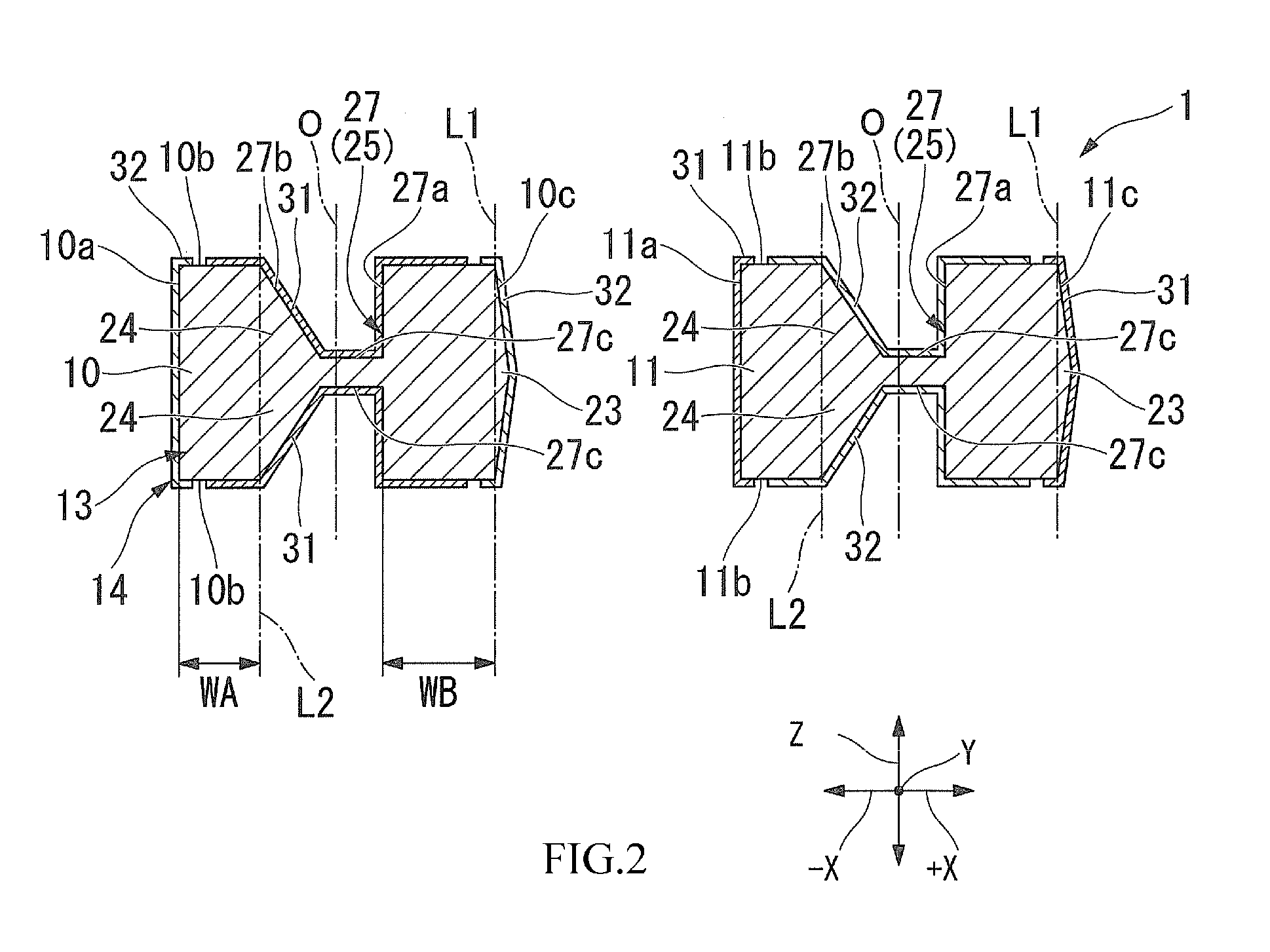
[0041]FIG. 1 is a plan view of a piezoelectric vibrating piece according to the embodiment of the present invention and FIG. 2 is a cross-sectional view taken along A-A line of FIG. 1.

[0042]As shown in FIG. 1 and FIG. 2, a piezoelectric vibrating piece 1 according to the embodiment is a tuning-fork type vibrating piece made of a piezoelectric material such as quartz crystal, lithium tantalate and lithium niobate, including a piezoelectric plate 13 having a base portion 12 integrally fixing a pair of vibrating arm portions 10, 11 and base end portions of the pair of vibrating arm portions 10, 11, and an electrode film 14 formed on the piezoelectric plate 13. The piezoelectric plate 13 according to the embodiment is formed by slicing a Lambert ore of quartz crystal at a given angle with respect to an X axis, a Y axis and a Z axis orthogonal to one another as crysta...


PUM


Abstract

A piezoelectric vibrating piece, a piezoelectric vibrator, an oscillator, an electronic apparatus and a radio timepiece capable of reducing the size while suppressing reduction of rigidity and having excellent vibration characteristics. The piezoelectric vibrating piece includes a pair of vibrating arm portions in parallel to each other, a base portion integrally fixing base end portions of the pair of vibrating arm portions in a length direction, groove portions on main surfaces of the pair of vibrating arm portions and extending along the length direction, where each of the groove portions includes a first groove portion near a tip portion end of the vibrating arm portions and a second groove portion near the base end portion side of the vibrating arm portions with respect to the first groove portion, and the second groove portion is offset in a −X axis direction with respect to the first groove portion.

Description

RELATED APPLICATIONS[0001]This application claims benefit of priority under 35 U.S.C. §119 to Japanese Patent Application No. 2012-204611, filed Sep. 18, 2012, the entire content of which is hereby incorporated by reference.BACKGROUND OF THE INVENTION[0002]1. Field of the Invention[0003]The present invention relates to a piezoelectric vibrating piece, a piezoelectric vibrator, an oscillator, an electronic apparatus and a radio timepiece.[0004]2. Description of the Related Art[0005]In a cellular phone or portable information terminal devices, a piezoelectric vibrator using quartz crystal and so on is used as a time source, a timing source of a control signal, a reference-signal source and so on. Various types of piezoelectric vibrators have been provided, and a piezoelectric vibrator having a so-called tuning-fork type piezoelectric vibrating piece is known as one of the piezoelectric vibrators.[0006]FIG. 16 is a cross-sectional view showing a related-art piezoelectric vibrating piec...

Claims


Application Information

Patent Timeline
Patent Type & Authority Applications(United States)
IPC IPC(8): H01L41/09G04R60/00
CPCG04R60/00H01L41/09H03H9/215H03H2003/026H03H9/1021G04R20/10G04C3/12H10N30/20
Inventor KOBAYASHI, TAKASHI
Owner SII CRYSTAL TECH
Why Eureka
Try Eureka