Shaft Arrangement and Method for Producing a Shaft Arrangement and Connecting Element as an Initial Product

a technology of shaft and connecting element, which is applied in the direction of shaft, shaft connection, coupling, etc., can solve the problems of increasing the difficulty of maintenance, insufficient strength of pure adhesive, and significant weakening of the shaft tube particularly in the connecting region,

Active Publication Date: 2014-03-20
SCHAEFER MWN
View PDF4 Cites 9 Cited by
  • Summary
  • Abstract
  • Description
  • Claims
  • Application Information

AI Technical Summary

Problems solved by technology

Since increasingly more wind power plants are installed in coastal marine areas, their maintenance again becomes considerably more difficult.
A pure adhesive would not suffice on account of the insufficient strength for the transmission of very high levels of torque.
A disadvantageous drilling through of a shaft tube consisting of fiber composite material for the screw fastening or secure connection to the connecting element would cut through a multiplicity of fiber bundles and therefore bring about a significant weakening of the shaft tube particularly in the connecting region.
The alternative possibility of butt welding of retaining pins is seen to be disadvantageous with regard to change of load in respect to torsion of the shaft arrangement.
On the other hand, the specific force transmission characteristics of the fiber bundles, which as a result of excessively frequent and excessively sharp changes of direction are rather impaired, are still taken well into consideration.

Method used


Image

  • Shaft Arrangement and Method for Producing a Shaft Arrangement and Connecting Element as an Initial Product
  • Shaft Arrangement and Method for Producing a Shaft Arrangement and Connecting Element as an Initial Product
  • Shaft Arrangement and Method for Producing a Shaft Arrangement and Connecting Element as an Initial Product

Examples


Embodiment Construction

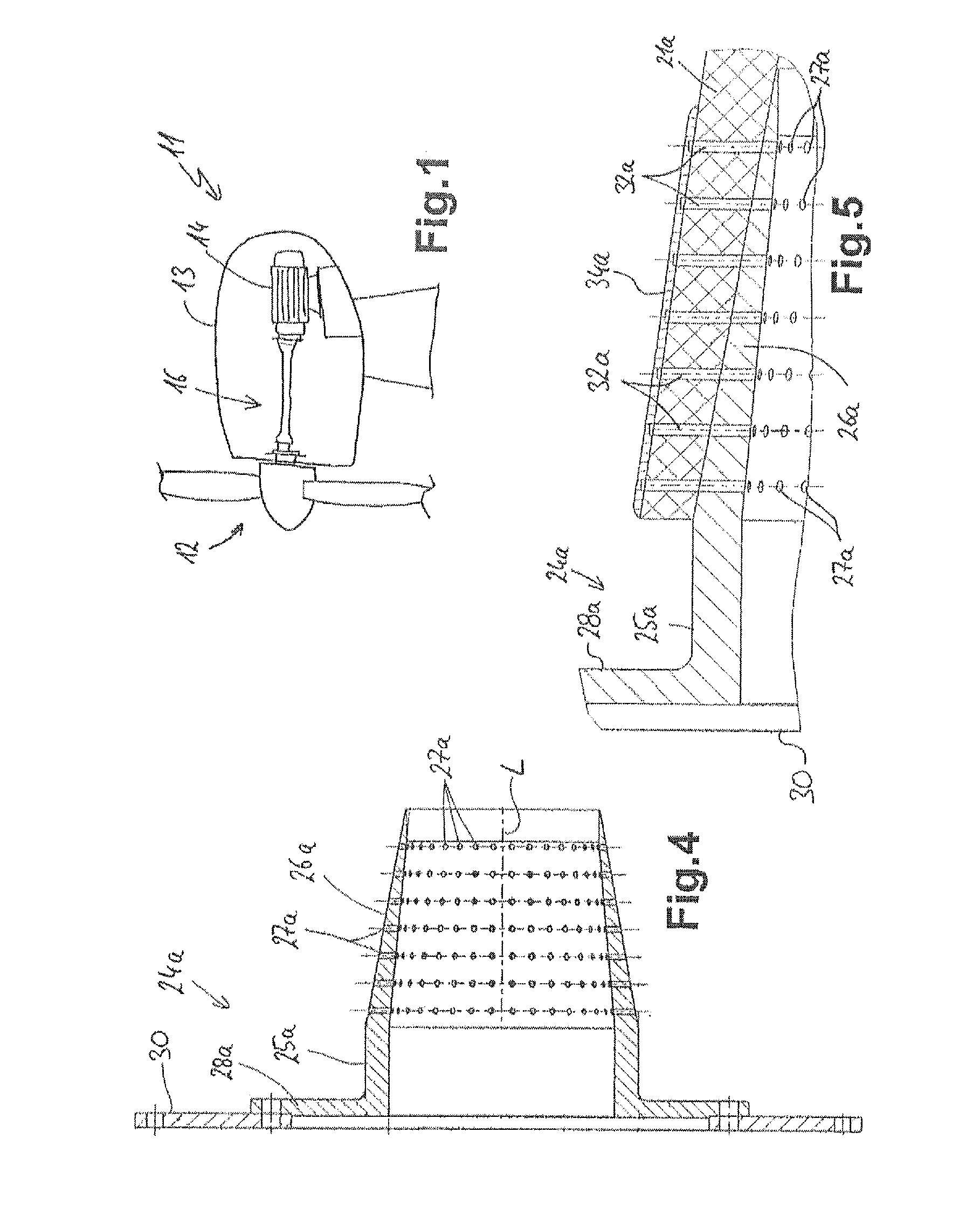
[0045]In FIG. 1, a wind power plant 11 is shown greatly simplified in side section. A rotor hub 12 is supported as is customary on the front end of a nacelle 13 which also contains a generator 14. Rotor hub 12 and generator 14 are interconnected in a rotation-resistant manner via a shaft arrangement 16, wherein no joints or other compensating devices at all are advantageously provided.

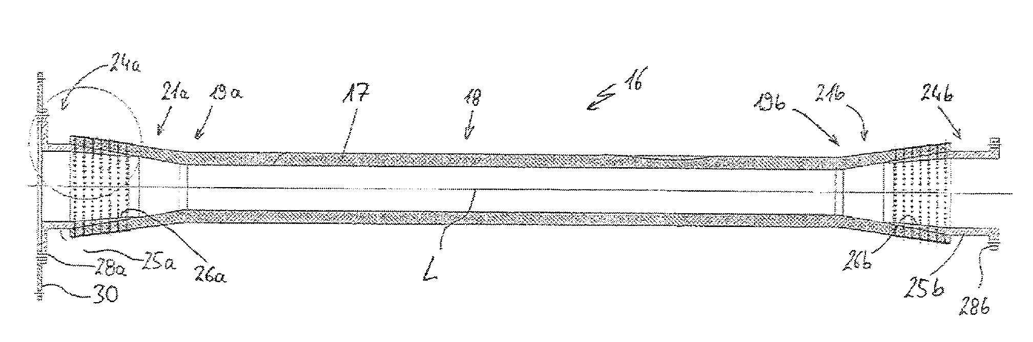
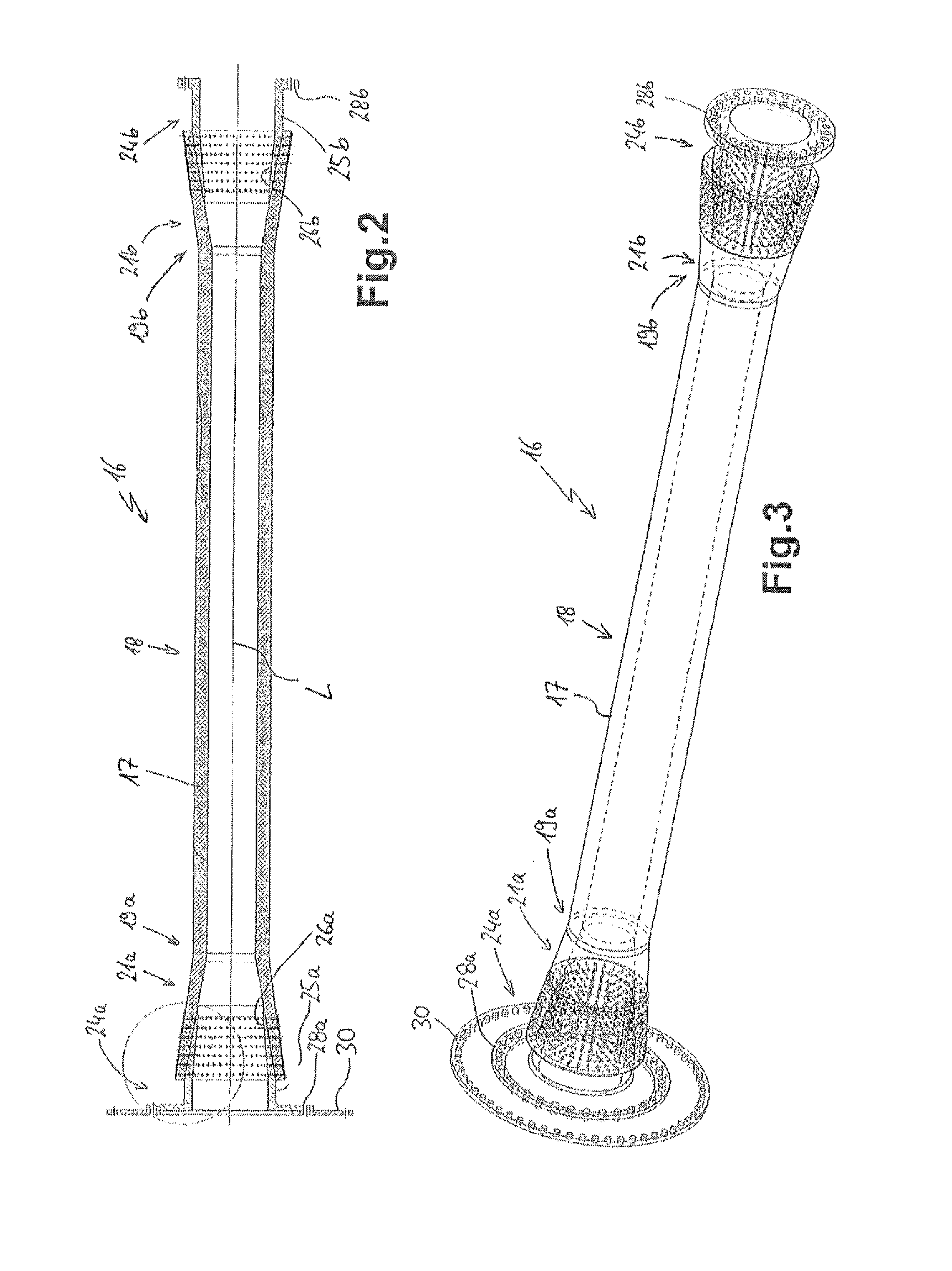
[0046]The shaft arrangement 16 according to the invention is shown enlarged in side section in FIG. 2 and in oblique view in FIG. 3 and has a shaft tube 17 which over a large part of its length 18 is formed by a middle region with constant band thickness and constant overall thickness. To the left, the shaft tube 17 merges via a left-hand transition region 19a into a left-hand conical flare 21a. On the right-hand end, a mirror-symmetrical similar construction is provided, with a right-hand transition region 19b and a right-hand conical flare 21b. The shaft tube 17 consists of a fiber composite material...


PUM


Abstract

A shaft arrangement for transmitting torques from a hub of a wind power plant to a generator has connecting elements at both ends for a mechanical connection. The connecting elements are each overlapped by end regions of a connecting shaft tube, wherein the shaft tube consists of a fibre composite material having a plurality of bundles of fibre. In the region overlapped by the shaft tube, the connecting elements have a plurality of protruding retaining pins about which and between which the bundles of fibre are placed and extend.

Description

FIELD OF APPLICATION AND BACKGROUND OF THE INVENTION[0001]The invention relates to a shaft arrangement for transmitting torque, and also to a method for producing such a shaft arrangement and to a connecting element as a semi-finished product for producing a shaft arrangement. Such a shaft arrangement is especially preferably used in wind power plants in order to connect a rotor hub to a generator.[0002]In the case of the aforesaid intended purpose, very high demands are made on the shaft arrangement. On the one hand, the torque which is to be transmitted is very large in view of wind power plants with increasingly larger rotor diameters. At the same time, a shaft arrangement should be as durable as possible, or the maintenance cost for the shaft arrangement and its supporting and the like should be as low as possible since maintenance is naturally very costly in the case of wind power plants. Since increasingly more wind power plants are installed in coastal marine areas, their mai...

Claims


Application Information

Patent Timeline
Patent Type & Authority Applications(United States)
IPC IPC(8): F16C3/02F16D1/02
CPCF16D1/02F16C3/026F16C3/023F16C2360/31Y10T403/7075
Inventor SOHL, CARSTEN
Owner SCHAEFER MWN
Why Eureka
Try Eureka