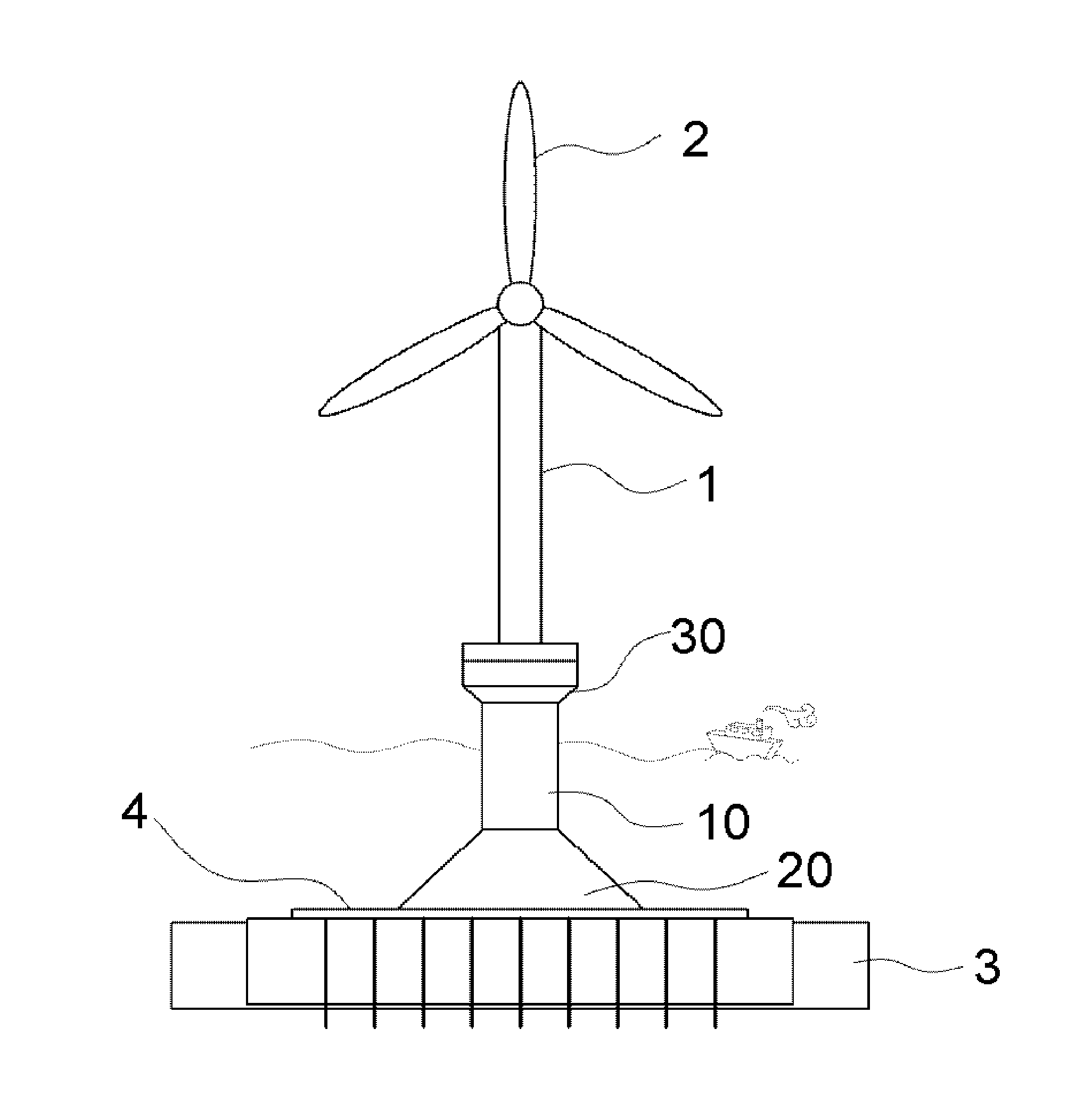
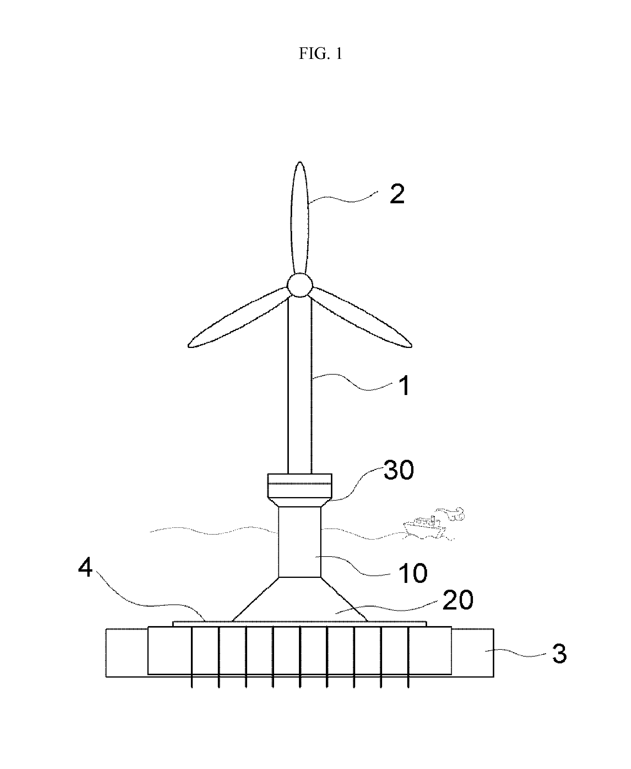
Supporting structure for offshore wind power generator
a technology of supporting structure and generator, which is applied in the direction of wind energy generation, artificial islands, construction, etc., can solve the problems of reducing price competitiveness, unable to obtain international certification, and reducing the contribution of bending resistance, so as to enhance the rigidity and ductility of the structure, reduce the amount of material and weight, and reduce the effect of bending resistan
- Summary
- Abstract
- Description
- Claims
- Application Information
AI Technical Summary
Benefits of technology
Problems solved by technology
Method used
Image
Examples
first embodiment
[0035]As shown in FIG. 4A, in the first embodiment, a shear key 40a and a shear key depression 50a are provided in corresponding ends of the main-body concrete parts 11 of the units a that face each other. The shear key 40a has a protrusion shape and comprises a plurality of shear keys 40a. The shear key depression 50a comprises a plurality of shear key depressions 50a which correspond to the respective shear keys 40a. Facing each other, the shear keys 40a and the shear key depression 50a are provided in the main-body concrete parts 11 of the upper and lower units a so that the upper and lower units a can be assembled with each other in an insert coupling manner. In this case, different kinds of methods can be used to fasten the shear keys 40a and the shear key depressions 50a to each other and, for example, mortar may be used.
[0036]Preferably, the number of shear keys 40a and the number of shear key depressions 50a are changed in response to bending moment applied to a junction J b...
third embodiment
[0038]FIG. 4C illustrates the present invention. In this embodiment, a shear key 40c and a shear key depression 50c are provided in corresponding ends of the main-body concrete parts 11 of the units a, wherein the shear key 40c comprises a plurality of shear keys 40c each of which has a bar shape that protrudes from the main-body concrete part 11, and the shear key depression 50c comprises a plurality of shear key depressions 50c which are configured corresponding to the respective shear keys 40c so that the bar-shaped shear keys 40c are inserted into the respective shear key depressions 50c. In other words, each shear key 40c is a bar that is made of steel or the like and is inserted into or attached to an end of the main-body concrete part 11. An attaching end made of steel may be formed by the shear key 40c in the end of the main-body concrete part 11, although it is not designated by a reference numeral. In this case, each shear key depression 50c is formed by forming a depressi...
fourth embodiment
[0039]FIG. 5A illustrates the present invention. In this embodiment, a support 60 that has a plate shape is attached to a circumference of the junction J between the upper and lower units a so that the upper and lower units a can be coupled to each other. In detail, it is preferable that the plate-shaped support 60 be attached to the circumference of the junction J between the units a so as to prevent the junction J between the units from becoming brittle.
[0040]The support 50 is attached to the junction J between the units a and is preferably made of FRP because it must have corrosion resistance. A known technique, for example, using adhesive, can be used to attached the support 50 to the junction J between the units a and, therefore, further explanation thereof will be omitted.
[0041]FIG. 5B illustrates another embodiment. In this embodiment, a connector 70 that has an H-shaped cross-section is provided in the junction J between the upper and lower units a so as to fasten the upper ...
PUM
 Abstract
Description
Claims
Application Information
 - R&D
- Intellectual Property
- Life Sciences
- Materials
- Tech Scout
- Unparalleled Data Quality
- Higher Quality Content
- 60% Fewer Hallucinations
Browse by: Latest US Patents, China's latest patents, Technical Efficacy Thesaurus, Application Domain, Technology Topic, Popular Technical Reports.
© 2025 PatSnap. All rights reserved.Legal|Privacy policy|Modern Slavery Act Transparency Statement|Sitemap|About US| Contact US: help@patsnap.com


