Permanent magnet type cylindrical molten-metal agitator and melting furnace with permanent magnet type suction pump

a technology of molten metal agitator and cylindrical molten metal agitator, which is applied in the direction of furnaces, charge manipulation, lighting and heating apparatus, etc., can solve the problems of abrasion of the rotary blade, large power consumption or complex maintenance of the electromagnetic coil, and high initial cost, so as to reduce the amount of generated heat, easy to use, and easy maintenance

Active Publication Date: 2014-03-20
TAKAHASHI KENZO
View PDF3 Cites 8 Cited by
  • Summary
  • Abstract
  • Description
  • Claims
  • Application Information

AI Technical Summary

Benefits of technology

[0006]The invention has been made to solve the above-mentioned problems, and an object of the invention is to provide an energy-saving agitator that suppresses the amount of generated heat, is easy to use due to easy maintenance, has flexibility in an installation position, and can also adjust an agitating ability, and a melting furnace with a permanent magnet type suction pump.

Problems solved by technology

However, the device using the electromagnetic coil required large power consumption or complex maintenance and had a problem in that initial costs are high.
Further, in the case of the mechanical agitator, there have been many problems in that the abrasion of the rotary blades is apt to occur, the costs for the replacement of the rotary impeller are very high per year, the stop of the furnace for a long time during the replacement cannot be avoided, and loss caused by down time is considerable, and the like.
However, there also is a problem in that performance is limited due to the heat generated from a furnace reinforcing plate, which is made of stainless steel.

Method used


Image

  • Permanent magnet type cylindrical molten-metal agitator and melting furnace with permanent magnet type suction pump
  • Permanent magnet type cylindrical molten-metal agitator and melting furnace with permanent magnet type suction pump
  • Permanent magnet type cylindrical molten-metal agitator and melting furnace with permanent magnet type suction pump

Examples


first embodiment

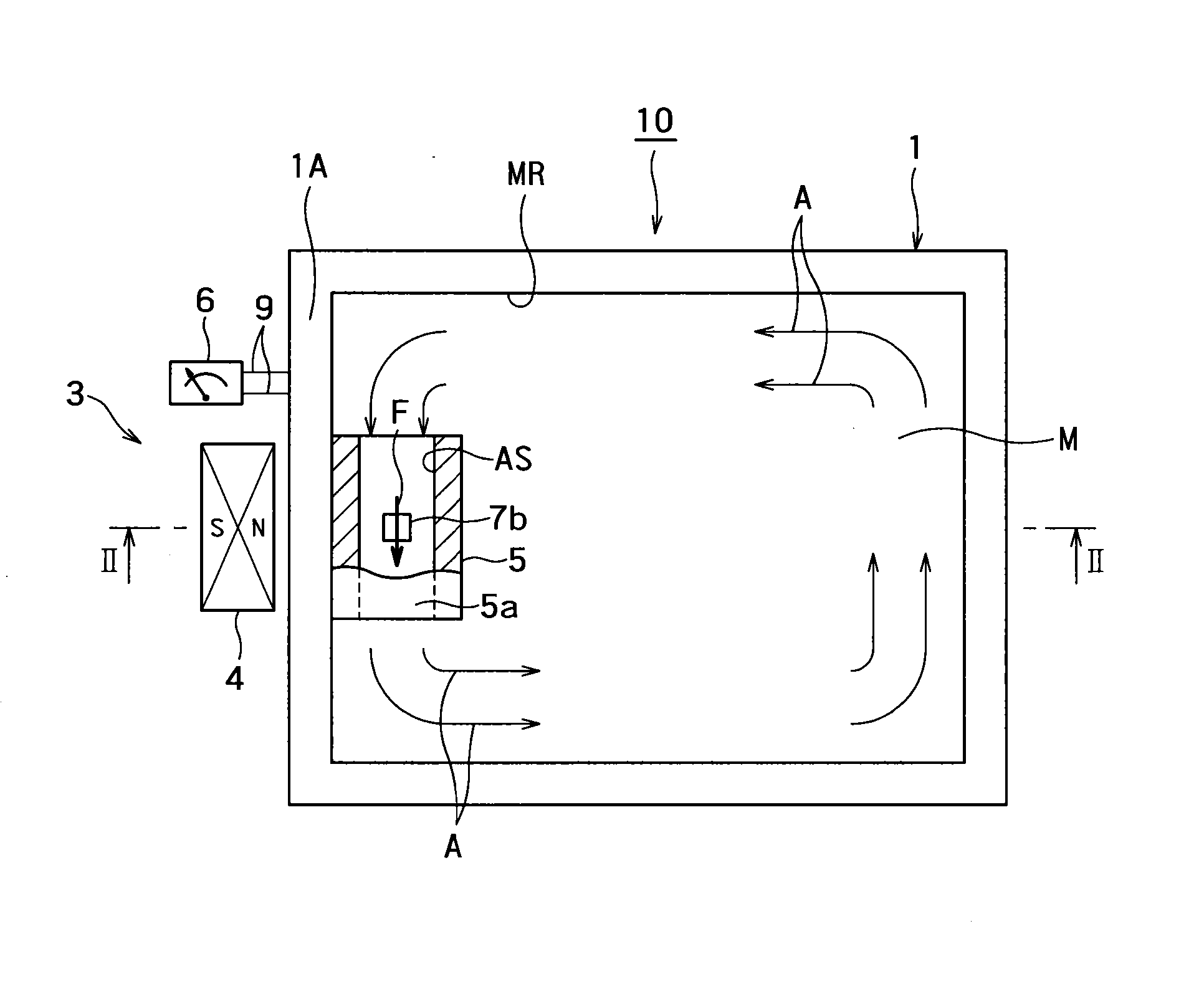
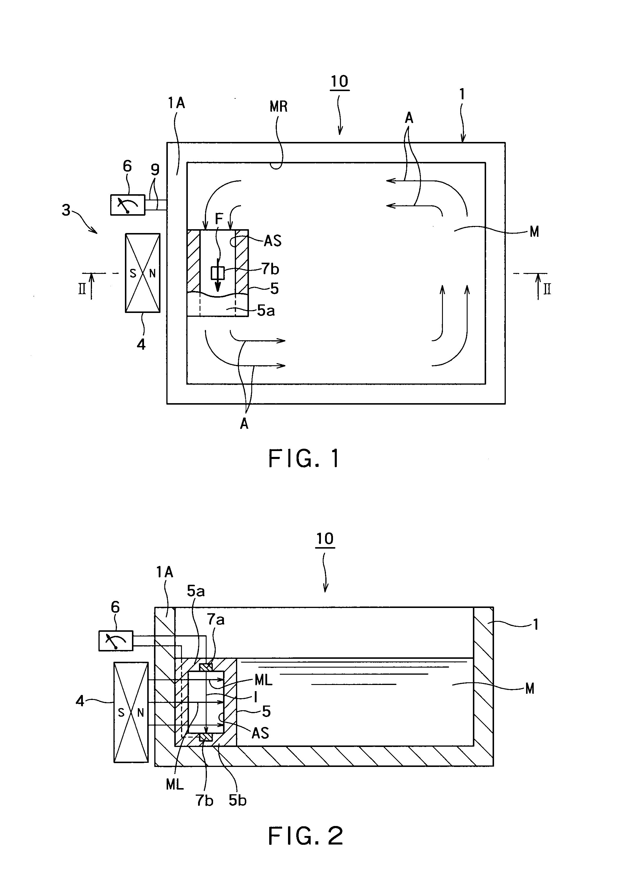
[0027]FIG. 1 is a plan view of the invention and FIG. 2 is a longitudinal cross-sectional view taken along line II-II of FIG. 1.

[0028]As understood from FIG. 1, a permanent magnet type molten-metal agitator 10 according to this embodiment includes a furnace body 1 that includes a molten metal room MR, and a agitating unit 3 that is mounted on the furnace body 1.

[0029]The agitating unit 3 includes a permanent magnet type magnetic field unit 4, a cylindrical molten-metal driving room-forming part 5, and a power source control panel 6 connected to a power source. The magnetic field unit 4 is a so-called single-pole permanent magnet. The magnetic field unit 4 is provided outside a side wall 1A of the furnace body 1, the molten-metal driving room-forming part 5 is provided in the furnace body 1, and the power source control panel 6 is provided at an arbitrary position outside the furnace body 1. Particularly, as understood from FIG. 1, the agitating unit 3 is to rotationally drive counte...

third embodiment

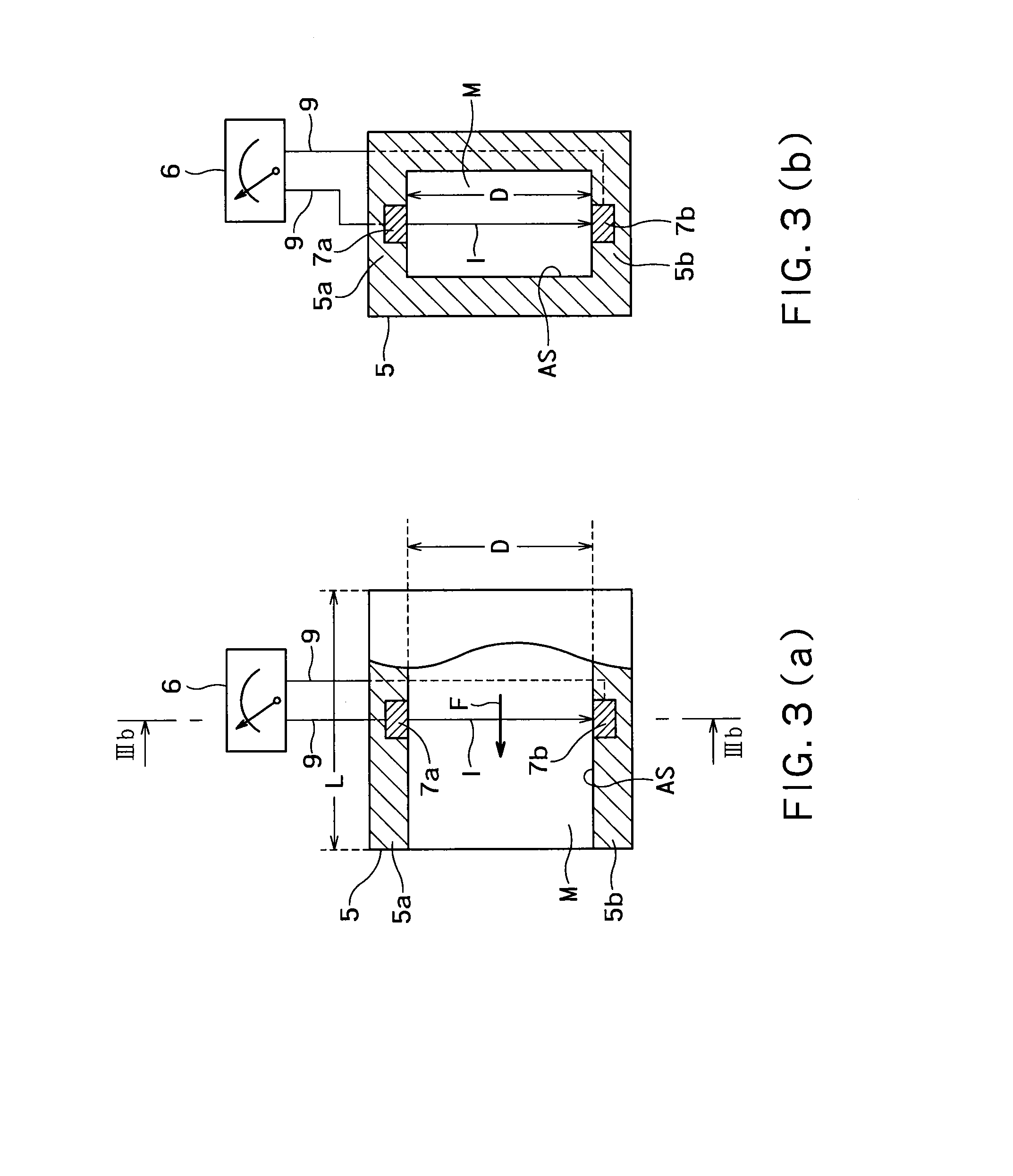
[0035]FIGS. 5(a) and 5(b) illustrate a third embodiment where molten metal M stored in a furnace body 1 is rotationally driven in a vertical direction as illustrated by arrows A in FIG. 5(b). FIG. 5(a) is a plan view and FIG. 5(b) is a longitudinal cross-sectional view taken along line Vb-Vb of FIG. 5(a). In this embodiment, current I and magnetic lines ML of force are generated so that an electromagnetic force F for allowing molten metal M to be sucked from below and discharged to the upper side by a molten-metal driving room-forming part 5 is generated as illustrated in FIG. 5(b). This will be described in more detail below.

[0036]The molten-metal driving room-forming part 5 illustrated in FIGS. 3(a) and 3(b) is assembled in a furnace body 1 in a so-called upright state by intended means. As understood from FIG. 5(a), current I flows between electrodes 7a and 7b in a vertical direction in FIG. 5(a) and the magnetic lines ML of force flow in a lateral direction in FIG. 5(a). Accordi...

sixth embodiment

[0042]A molten-metal driving room-forming part 5B illustrated in FIG. 11 is used in the The molten-metal driving room-forming part 5B has the shape of a container of which only a top plate portion among six surfaces is opened, and is mounted while electrodes 7a and 7b protrude from the inner surface of a bottom plate 5Ba. On the other hand, particularly, as understood from FIG. 9, a side wall 101A of a furnace body 101 is provided with an outlet 101a from which molten metal M stored in the furnace body flows out and an inlet 101b through which molten metal M flows into the furnace body from the outside. However, as understood from FIGS. 9 and 10, the molten-metal driving room-forming part 5B illustrated in FIG. 11 is hermetically mounted on the side wall 101A of the furnace body 101 from the outside. Further, as in each of the above-mentioned embodiments, a magnetic field unit 4 is provided so as to face the electrodes 7a and 7b in the lateral direction in FIG. 10 with the bottom p...


PUM

PropertyMeasurementUnit
magnetic fieldaaaaaaaaaa
shapeaaaaaaaaaa

Abstract

There is provided an energy-saving agitator that suppresses the amount of generated heat, is easy to use and carry out maintenance, has flexibility in an installation position, and can also adjust an agitating ability. The agitator includes a furnace body that includes a molten metal room storing a molten metal, and an agitating unit that agitates the molten metal stored in the furnace body. The agitating unit includes a molten-metal driving room-forming part that is disposed in the molten metal room, applies a driving force to the molten metal, and forms a driving room of which both ends are opened; a pair of electrodes that is disposed in the driving room and makes current flow in the driving room under the presence of the molten metal; and a magnetic field unit which is formed of a permanent magnet disposed outside the furnace body, of which one pole of an N pole and an S pole faces the furnace body so that magnetic lines of force generated from the one pole cross the current, and which generates an electromagnetic force for driving the molten metal from one end toward the other end in the driving room.

Description

TECHNICAL FIELD[0001]The present invention relates to a permanent magnet type cylindrical molten-metal (melt) agitator that agitates molten metals of Al, Cu, Zn, Si, or an alloy of at least two of them, an Mg alloy, other metal, or the like; and a melting furnace with a permanent magnet type suction pump.BACKGROUND ART[0002]In the past, an electromagnetic agitator that generates a shifting field by making low-frequency current or high-frequency current flow in an electromagnetic coil in order to agitate a molten metal, a mechanical agitator that directly agitates the molten metal by a rotary impeller inserted into the molten metal, or the like has been used to agitate the molten non-ferrous metal or other metal. The main objects of all these devices are to uniformize the composition of the molten metal present in a furnace, to uniformize the temperature distribution of the molten metal, to reduce the time for melting in a melting furnace, and the like.[0003]However, the device using...

Claims


Application Information

Patent Timeline
Patent Type & Authority Applications(United States)
IPC IPC(8): F27D27/00
CPCF27D27/005F27D3/14H02K44/04B22D45/00F27D27/00
Inventor TAKAHASHI, KENZO
Owner TAKAHASHI KENZO
Why Eureka
Try Eureka