
Cell reconfiguration

a cell and cell technology, applied in the field of cell reconfiguration, can solve the problems of serious affecting the experience of users, raising a new issue for mobile (moving) relay nodes, and not specified any solution, so as to avoid or reduce the negative impact of user equipmen

Active Publication Date: 2014-03-20
NOKIA TECHNOLOGLES OY
View PDF3 Cites 49 Cited by
  • Summary
  • Abstract
  • Description
  • Claims
  • Application Information

AI Technical Summary

Benefits of technology

The patent is about a method for reconfiguring a mobile station (relay node / cell) without affecting the user equipment currently using it. The method involves detecting synchronization failures and updating the user equipment with the new synchronization failure values after the configuration change is completed. The technical effect of this patent is to minimize the impact on user equipment when a mobile relay node / cell is reconfigured.

Problems solved by technology

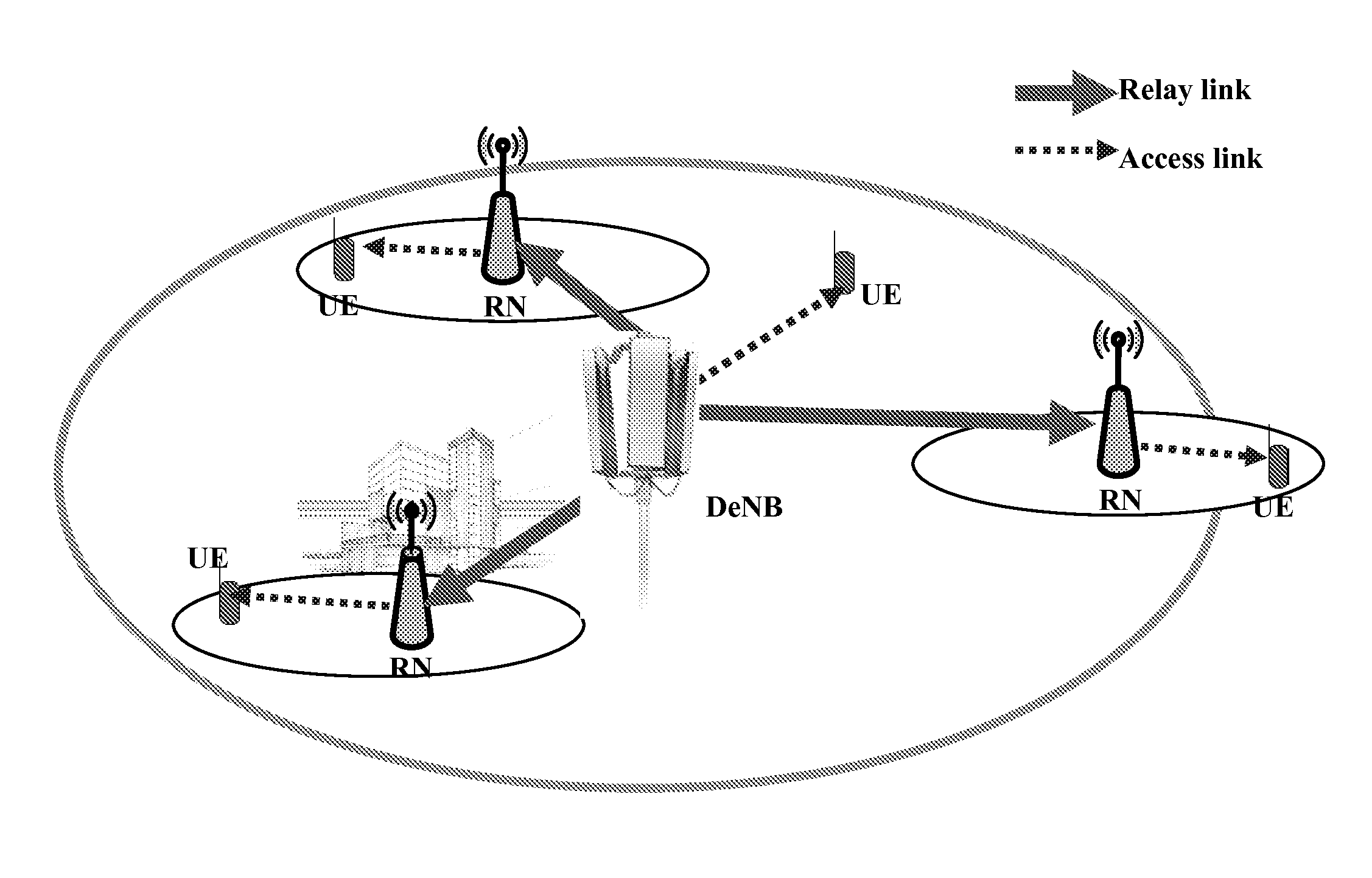
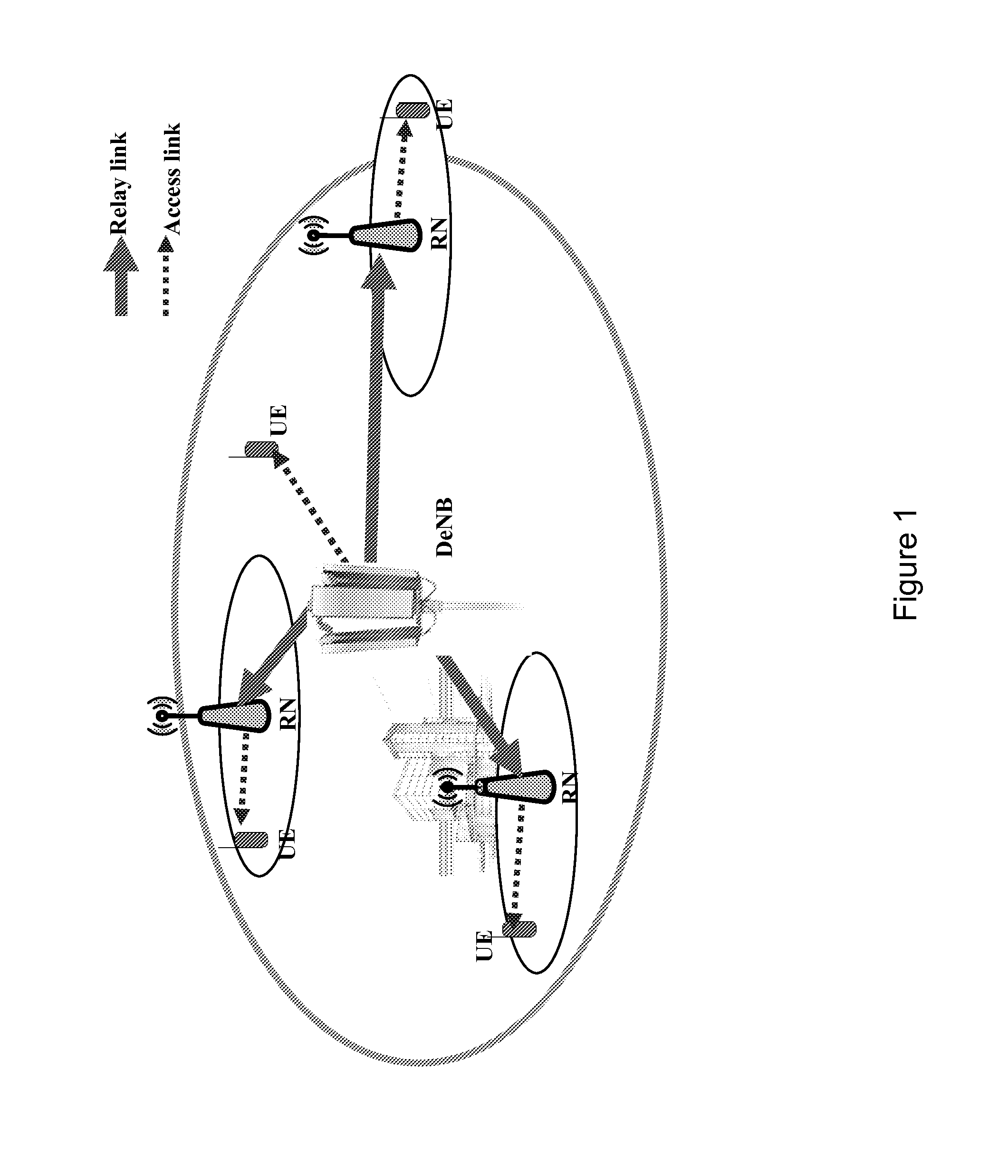
Given that many UEs could be served by the relay node cell during the moving period, the change of the PCI on the fly raises a new issue for mobile (moving) relay nodes.
Namely, the change of the PCI would typically interrupt the service continuation of UE / UEs currently served by the relay node due to a radio link failure (RLF) detected by the UE / UEs.
This long interruption time (delay) would seriously impact the experience of users.
Accordingly, there is currently not specified any solution to the above-outlined issues and problems of mobile (moving) relay nodes.
However, this is not always possible, e.g. in case the neighboring cells are overloaded, and the UEs connected to the RN would thus experience a radio link failure and service interruption.
The UEs served by the relay node could typically be moving with the moving relay node, and the signal from neighboring nodes might be strongly attenuated by the vehicle upon which the relay node is installed, which is why handing over these UEs to the DeNB or other nodes might spoil the performance in the neighboring cells.
Thereby, PCI confusion and collision between relay nodes and other neighboring cells could be avoided, but there would still exist a problem of a potential PCI confusion and / or collision between different relay nodes.
In view thereof, there do not exist any mechanisms for enabling cell reconfiguration (for example, in a relay-enhanced network environment) in a proper an efficient manner.

Method used


Image

  • Cell reconfiguration
  • Cell reconfiguration
  • Cell reconfiguration

Examples


Embodiment Construction

[0023]Embodiments of the present invention aim at addressing at least part of the above issues and / or problems and drawbacks.

[0024]Embodiments of the present invention are made to provide mechanisms for enabling cell reconfiguration (for example, in a relay-enhanced network environment) in a proper an efficient manner.

[0025]This may for example be achieved by the subject-matter defined in the attached claims.

[0026]According to an exemplary first aspect of the present invention, there is provided a method comprising recognizing a decision on a change of a configuration of a base station, informing a user equipment served by the base station in view of a forthcoming change of the configuration before the configuration of the base station is changed, and providing the user equipment being served by the base station with a synchronization signal indicating a new configuration after the configuration of the base station is changed from an old configuration to the new configuration.

[0027]...


PUM


Abstract

There are provided measures for a cell reconfiguration, more specifically a cell reconfiguration in a relay-enhanced network environment. Such measures exemplarily include recognizing a decision on a change of a configuration of a base station, informing a user equipment served by the base station in view of a forthcoming change of the configuration before the configuration of the base station is changed, and providing the user equipment being served by the base station with a synchronization signal indicating a new configuration after the configuration of the base station is changed from an old configuration to the new configuration.

Description

FIELD OF THE INVENTION[0001]The present invention relates to a cell reconfiguration. More specifically, the present invention may relate to a cell reconfiguration in a relay-enhanced network environment, namely a relay cell reconfiguration.BACKGROUND OF THE INVENTION[0002]In the development of radio communication systems, such as mobile communication systems, efforts are made for an evolution of the radio access part thereof. In this regard, the evolution of radio access networks (like for example the GSM EDGE radio access network (GERAN) and the Universal Terrestrial Radio Access Network (UTRAN) or the like) is currently addressed. Such improved radio access networks are sometimes denoted as evolved radio access networks (like for example the Evolved Universal Terrestrial Radio Access Network (E-UTRAN)) or as being part of a long-term evolution (LTE) or LTE-Advanced. Although such denominations primarily stem from 3GPP (Third Generation Partnership Project) terminology, the usage t...

Claims


Application Information

Patent Timeline
Patent Type & Authority Applications(United States)
IPC IPC(8): H04W24/02
CPCH04W24/02H04W48/08H04W84/005H04W84/047
Inventor ZHANG, SHUN LIANGREDANA, SIMONERAAF, BERNHARDDU, LEI
Owner NOKIA TECHNOLOGLES OY
Learn More