
System and method for controlling fuel cell system

Active Publication Date: 2014-03-20
HYUNDAI MOTOR CO LTD +1
View PDF37 Cites 13 Cited by
  • Summary
  • Abstract
  • Description
  • Claims
  • Application Information

AI Technical Summary

Benefits of technology

The present invention provides a system and method for controlling a fuel cell system that can supply air accurately to the fuel cell stack and prevent flooding and dry-out. This system and method can reduce unnecessary energy consumption, improve fuel efficiency, and prevent noise during a transition period. Fuel cell system performance is improved.

Problems solved by technology

In particular, depending on the amount of air, when the operating temperature is low, such as during start-up or warm-up of the fuel cell system, flooding (excessive condensation) may occur.
Furthermore, when the operating temperature increases, such as during high power operation, a polymer electrolyte membrane my dry out in the fuel cell stack.
However, excess air may still be supplied to the cathode in this control method.
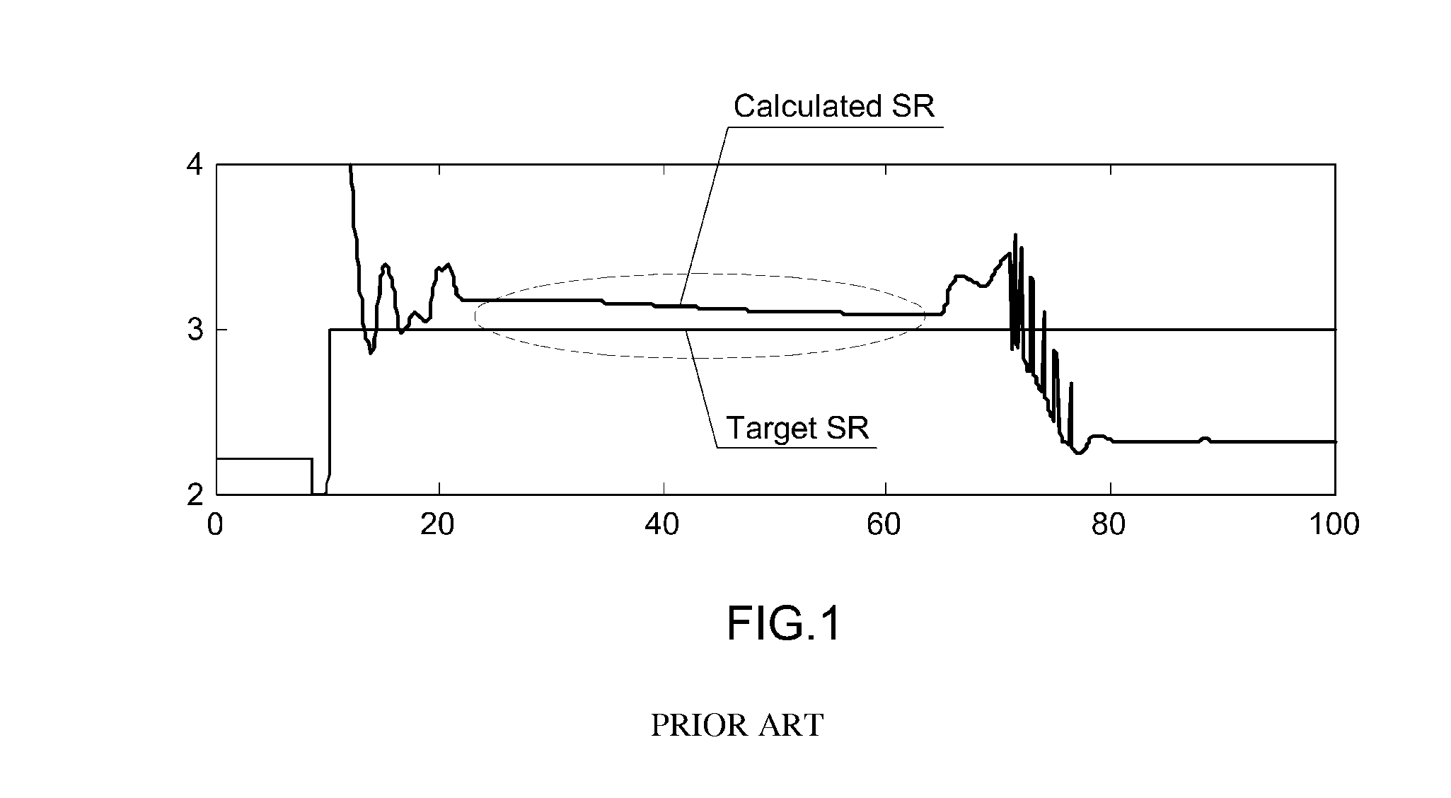
When the SR calculated under actual operating conditions is higher than the target SR, more than an optimum amount of air is supplied to the fuel cell stack (i.e., excessive supply of air).
This means that the air blower is being operated more than is necessary to reach a target value, which consumes much more energy than necessary for the operation of the air blower, thus reducing the fuel efficiency of the fuel cell vehicle.
Moreover, during the operation of the air blower, significant noise is generated, and the water balance in the fuel cell stack is affected due to the unnecessary excessive supply of to air, which may possibly cause the polymer electrolyte membrane to dry out, thus reducing the performance of the fuel cell.

Method used


Image

  • System and method for controlling fuel cell system
  • System and method for controlling fuel cell system
  • System and method for controlling fuel cell system

Examples


Embodiment Construction

[0033]Hereinafter reference will now be made in detail to various embodiments of the present invention, examples of which are illustrated in the accompanying drawings and described below. While the invention will be described in conjunction with exemplary embodiments, it will be understood that present description is not intended to limit the invention to those exemplary embodiments. On the contrary, the invention is intended to cover not only the exemplary embodiments, but also various alternatives, modifications, equivalents and other embodiments, which may be included within the spirit and scope of the invention as defined by the appended claims.

[0034]The terminology used herein is for the purpose of describing particular embodiments only and is not intended to be limiting of the invention. As used herein, the singular forms “a,”“an” and “the” are intended to include the plural forms as well, unless the context clearly indicates otherwise. It will be further understood that the t...


PUM


Abstract

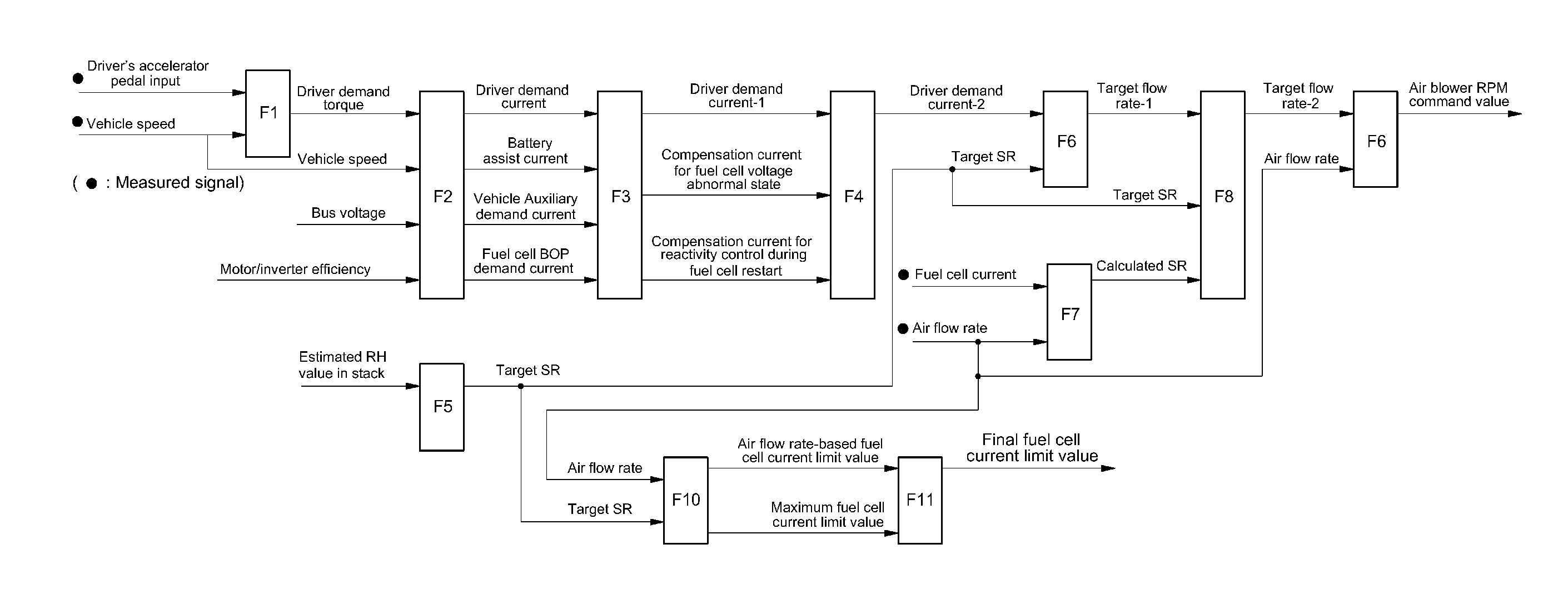
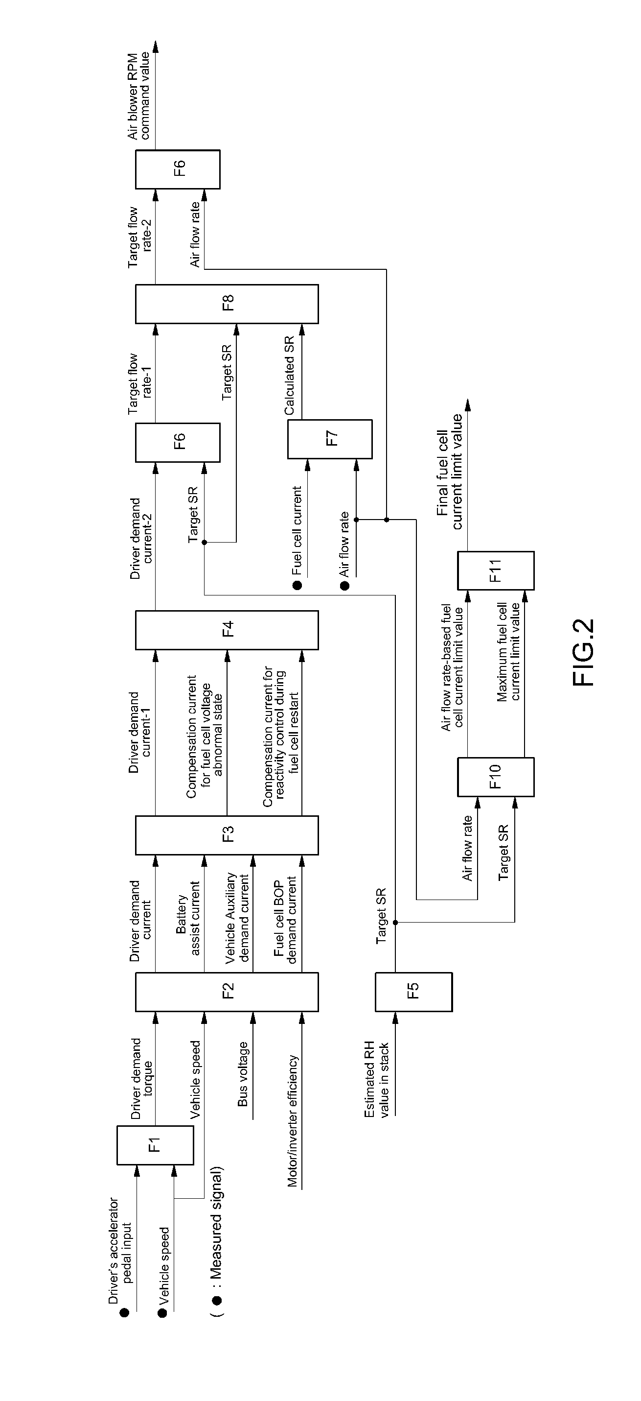
Disclosed is a system and method for controlling a fuel cell system. More specifically, a fuel cell demand current is calculated based on a driver demand current calculated from a driver demand torque. Then a target flow rate-1 of air to be supplied to a fuel cell stack is calculated based on the fuel cell demand current and a target stoichiometric ratio (SR) of air. The target flow rate-1 is then compensated for using the target SR, an RPM command value of an air blower is calculated based on a compensated target flow rate-2 and the amount of air currently measured. The operation of the air blower is subsequently controlled based on the calculated RPM command value.

Description

CROSS-REFERENCE TO RELATED APPLICATION[0001]This application claims under 35 U.S.C. §119(a) the benefit of Korean Patent Application No. 10-2012-0104243 filed Sep. 19, 2012, the entire contents of which are incorporated herein by reference.BACKGROUND[0002](a) Technical Field[0003]The present invention relates to a system and method for controlling a fuel cell system. More particularly, the present invention relates to a system and method for controlling a fuel cell system which minimizes excessive supply of air that is unintended and unnecessary and thus reduces unnecessary energy consumption for an operation of an air blower and improves fuel efficiency of a fuel cell vehicle as a result.[0004](b) Background Art[0005]A fuel cell system as applied to a hydrogen fuel cell vehicle typically includes a fuel cell stack for generating electricity via an electrochemical reaction between reactant gases, a fuel processing system (FPS) for supplying hydrogen as a fuel to the fuel cell stack,...

Claims


Application Information

Patent Timeline
IPC IPC(8): H01M8/04
CPCH01M8/04753H01M8/04395H01M8/04589H01M8/04604B60L58/31B60L50/72H01M8/04992H01M8/0491H01M2250/20Y02T90/40Y02E60/50B60K26/00H01M8/04B60L50/50
Inventor JEON, SOON ILKWON, SANG UK
Owner HYUNDAI MOTOR CO LTD
Learn More