
Inhalation anesthetic vaporizer

a technology of inhalation anesthetic and vaporizer, which is applied in the direction of inhalators, medical devices, other medical devices, etc., can solve the problems of reducing the concentration or volume percent delivered to the patient, further reducing the temperature of a traditional vaporizer chamber, and reducing the vaporizer output over time. , the effect of reducing the temperature of the chamber and the vaporization of the agen

Inactive Publication Date: 2014-03-27
PIRAMAL CRITICAL CARE
View PDF9 Cites 5 Cited by
  • Summary
  • Abstract
  • Description
  • Claims
  • Application Information

AI Technical Summary

Benefits of technology

The present invention describes a method for vaporizing anesthetic for inhalation. The method involves using a vaporizer with a thermally conductive container and a temperature sensor to maintain the anesthetic at a specific temperature. The vaporizer is connected to a breathing-gas delivery tube, and the anesthetic is partially filled in the container. The breathing-gas is introduced to the anesthetic to create a bubble. The temperature of the anesthetic is measured using the sensor and control circuitry, and if the temperature is too low, the heater provides heat to the container until it reaches the desired level. This process ensures safe and accurate vaporization of the anesthetic for inhalation.

Problems solved by technology

Regardless of the vaporizer setting, without thermal compensation, the vaporizer cools as the liquid anesthetic vaporizes, and results in a decrease in concentration, or volume percent delivered to the patient.
This heat of vaporization is supplied by the remaining anesthetic (temperature loss by the latent heat of vaporization) causing further drop in temperature of a traditional vaporizer chamber and decrease in vaporizer output over time.
This increased wicking increases the evaporation, which decreases the temperature of the chamber and agent vaporization.
However, during high-flow and / or long duration usage, both the temperature compensation for flow and vaporizer mass cannot control the energy loss in the system, which will decrease the vaporizer concentration in the chamber and reducing agent concentration from the vaporizer.
Moreover, these prior art conventional bypass type vaporizers are not suitable for use with desflurane, for reasons known to those of ordinary skill in the art.
This means that healthcare providers must purchase multiple vaporizers (one per agent), which may be cost-prohibitive in an era of cost containments and reimbursement cuts.
In addition, currently available commercial vaporizers are bulky, heavy, and / or complex to set up and maintain, and require tremendous logistical overhead to transport.

Method used


Image

  • Inhalation anesthetic vaporizer
  • Inhalation anesthetic vaporizer
  • Inhalation anesthetic vaporizer

Examples


Embodiment Construction

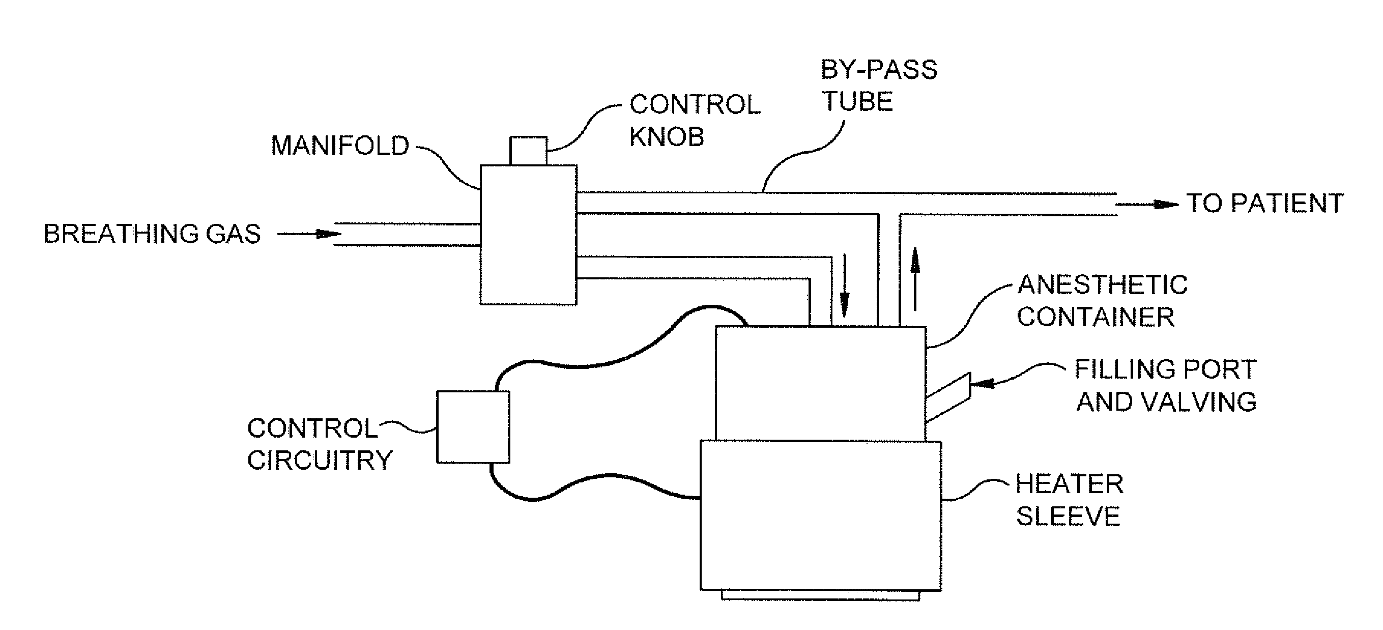
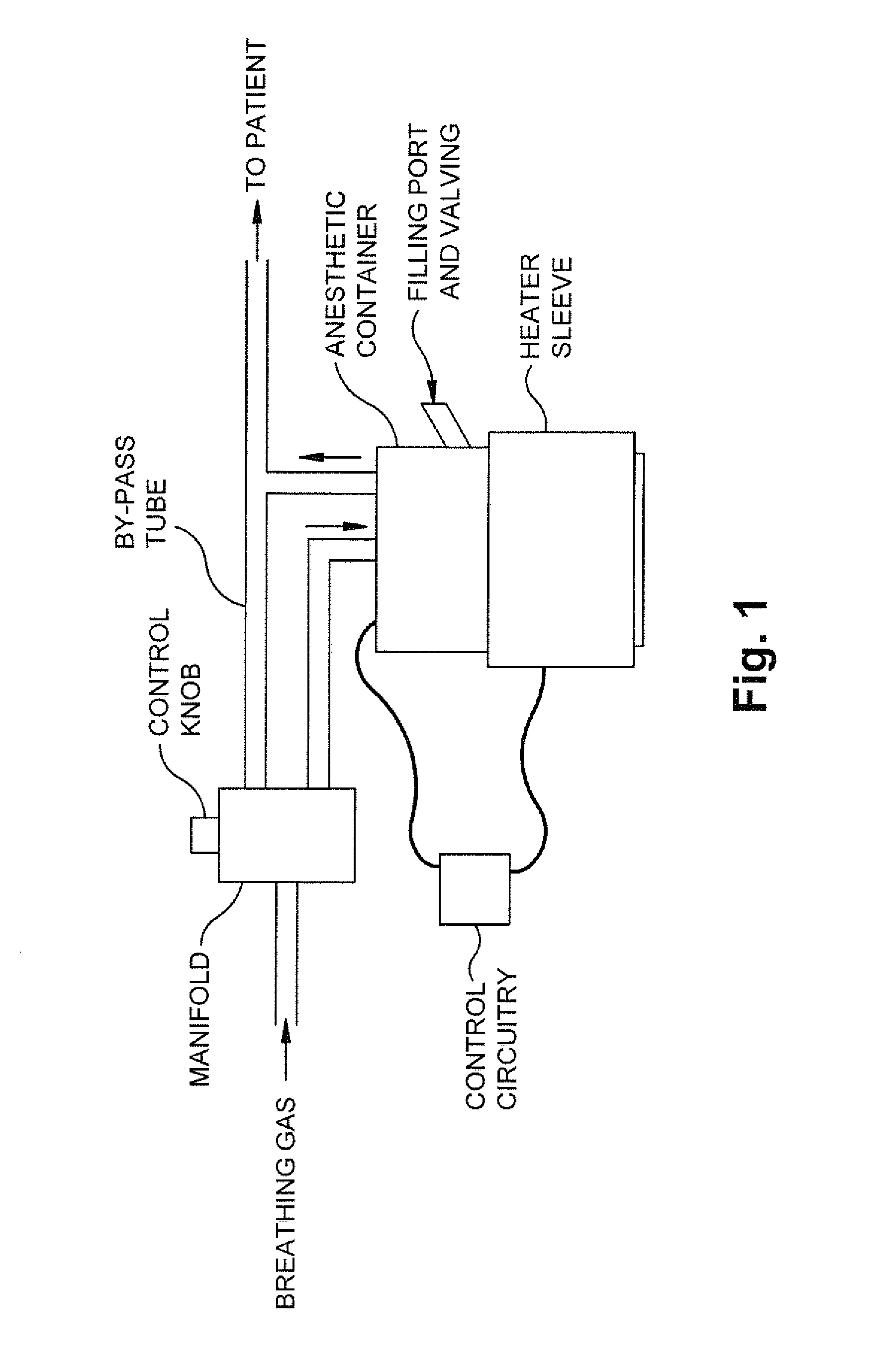
[0026]In accordance with the present invention, FIG. 1 depicts an anesthetic vaporizer. As described herein, the present invention addresses the challenges posed by prior art vaporizers, in that (i) latent heat of vaporization results in a drop in drug temperature that may result in a lower partial pressure, and (ii) lower partial pressure may result in lower concentration. The temperature of a given anesthetic for the device of FIG. 1 is a maintained at a set temperature ±0.5° C. or 1.0° C. (e.g., at 22° C.±0.5° C. or 22° C.±1.0° C.).

[0027]The vaporizer shown and described herein may incorporate at least the following aspects:

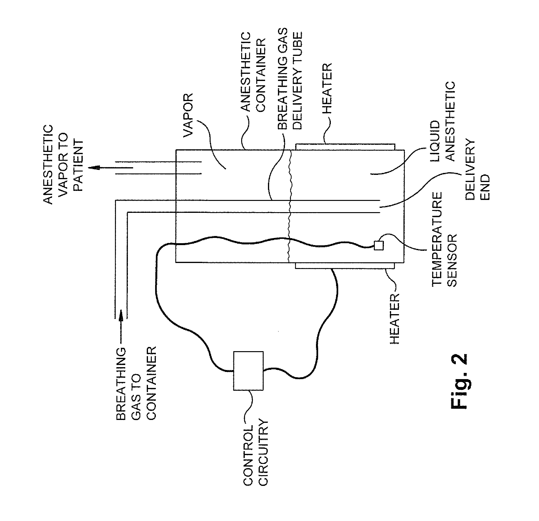
[0028]the vaporizer inflow tube is placed below the surface of the liquid anesthetic agent such that the outlet of the vaporizer inflow tube (or the delivery end of the delivery tube) is located anywhere from at least about 5 mm from the surface and no closer than about 2 mm (the term “about” in either of these instances being ±1 mm) to the bottom (relative to...


PUM


Abstract

A vaporizer includes a thermally conductive anesthetic container and a temperature sensor positioned in the container and in the liquid anesthetic. A breathing-gas delivery tube has a delivery end positioned in the liquid anesthetic at least about 5 mm beneath the top surface of the liquid anesthetic. A heater is positioned outside the container. Control circuitry is configured to receive signals from the temperature sensor and is connected to the heater in order to cause the heater to maintain the temperature of the anesthetic above a predetermined temperature. A method of vaporizing inhalation anesthetic is also provided.

Description

RELATED APPLICATION[0001]This application claims priority from U.S. Provisional Applications Nos. 61 / 705,965, filed 26 Sep. 2012, and 61 / 801,209, filed 15 Mar. 2013, the subject matter of both of which is incorporated herein by reference in its entirety.TECHNICAL FIELD[0002]The present invention relates to an apparatus and method for use of an inhalation anesthetic vaporizer.BACKGROUND OF THE INVENTION[0003]Inhalation anesthetics are commonly delivered to patients by a vaporizer.[0004]The scientific principles that relate the operation of a vaporizer include vapor pressure, boiling point of volatile liquid anesthetic agents, flow rate, gas concentration, heat of vaporization, specific heat, and thermal conductivity. An anesthetic vaporizer design may take into account these principles.[0005]It is known in the art that the vapor pressure of an anesthetic gas is affected by variables such as temperature and pressure. In the context of volatile liquid anesthetics, vapor pressure is the...

Claims


Application Information

Patent Timeline
Patent Type & Authority Applications(United States)
IPC IPC(8): A61M16/18
CPCA61M16/18A61M16/1075A61M2205/3368A61M2205/3653A61M16/109
Inventor ROBEL, RITCHIEBURNS, WILLIAMNORIJI, CHRISGWAZE, MICHAELCUZYDLO, MICHAEL
Owner PIRAMAL CRITICAL CARE
Learn More