Method for gravity separation of plastic particles and gravity separator for plastic particles

a gravity separator and plastic particle technology, applied in the direction of gas current separation, solid separation, sorting, etc., can solve the problems of not being able to provide the required homogeneity of magnetic fields in the respective devices, not being able to achieve the required homogeneity of magnetic fields, and not being able to achieve the required homogeneity in the respective devices. , to achieve the effect of accurately and efficiently adjusted and simple manner

Inactive Publication Date: 2014-03-27
KRONES AG
View PDF7 Cites 1 Cited by
  • Summary
  • Abstract
  • Description
  • Claims
  • Application Information

AI Technical Summary

Benefits of technology

[0007]Preferably, ionized gas is added to the separation gas, in particular with respect to the main direction of flow of the separation gas in the transverse stream. The ionized gas can also be added as needed at several points of the separation gas stream, so that electrostatic charges of the plastic particles can be effectively and efficiently reduced.
[0021]Preferably, at least two separately adjustable ion generators are provided. In this manner, the required ionization level can be accurately and efficiently adjusted to the plastic particles to be separated.

Problems solved by technology

However, the plastic particles to be separated can also be passively, i.e. inadvertently, charged to an undesired degree during transportation of the material, for example, by friction of the particles against the pipe wall.
However, magnetic fields can not be provided with the required homogeneity in the respective devices or only at great technical effort.
Therefore, facility areas usually form, in which the electrostatic charges of the plastic particles are not sufficiently removed, so that they accumulate in the respective areas in an undesired manner.
The high energy consumption associated with such methods is also disadvantageous.

Method used


Image

  • Method for gravity separation of plastic particles and gravity separator for plastic particles
  • Method for gravity separation of plastic particles and gravity separator for plastic particles
  • Method for gravity separation of plastic particles and gravity separator for plastic particles

Examples


Embodiment Construction

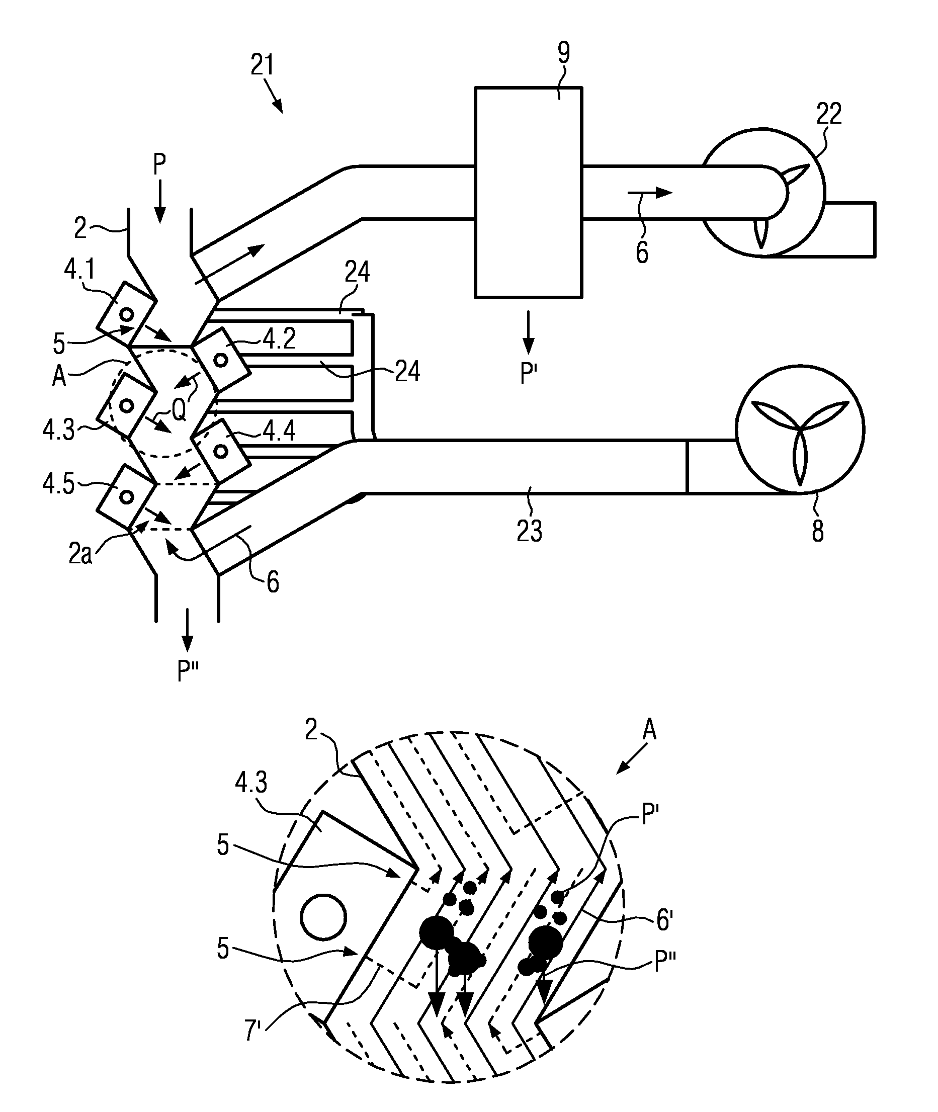
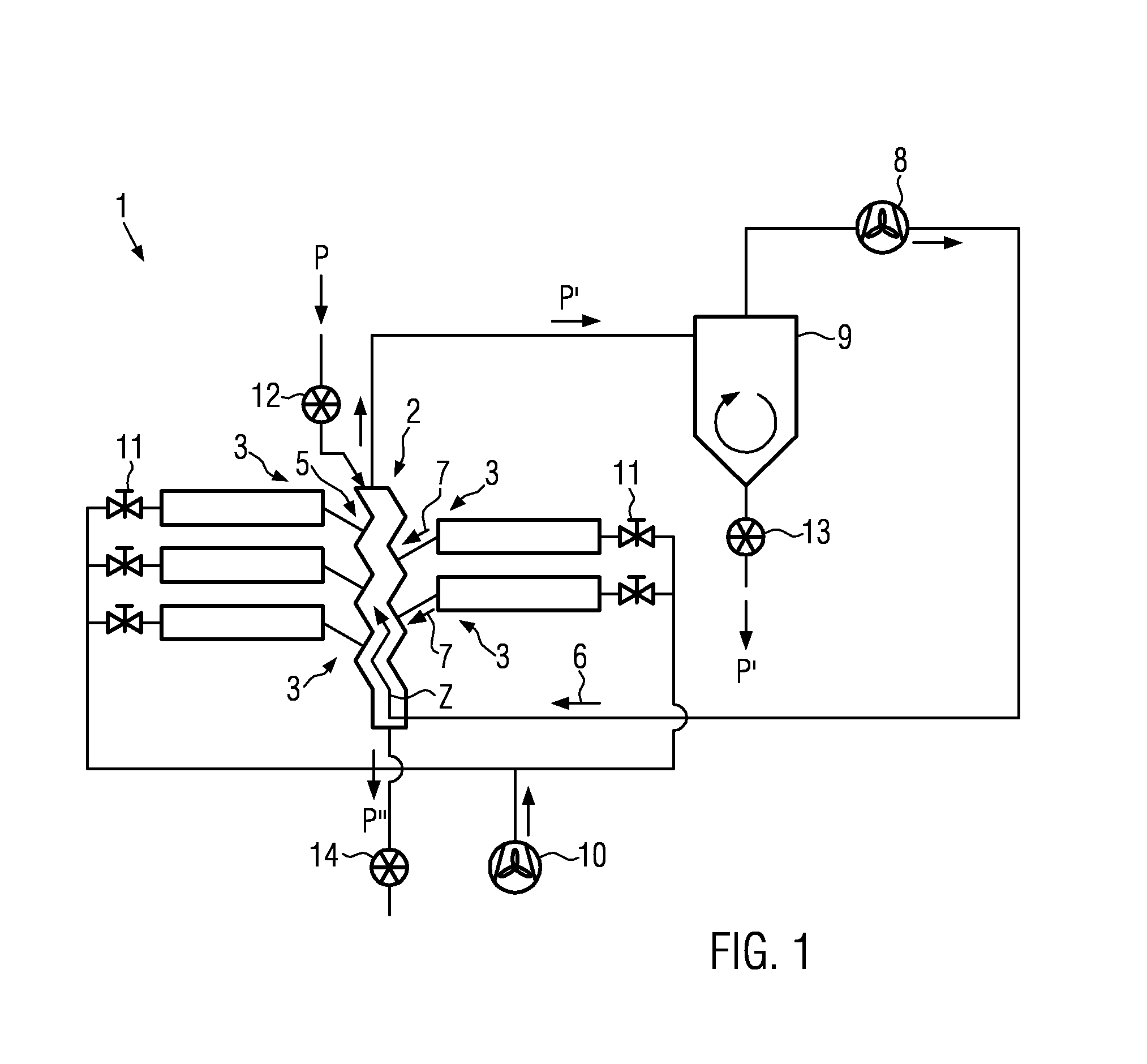
[0027]As shown in FIG. 1, a first embodiment 1 of the gravity separator according to the disclosure for plastic particles P comprises a separation duct 2, to which the ionization apparatuses 3 are connected. They comprise, for example, ion generators 4.1 to 4.5 shown in FIGS. 2 and 3 and inlet nozzles 5 connected thereto and leading into the separation duct 2. The separation duct 2 has separation gas 6 flowing through essentially in the counter stream to gravity, i.e. from below upwardly. Ionized gas 7 is generated by each ionization apparatus 3 and introduced into the separation duct 2 substantially in the transverse stream Q to the separation gas 6. The separation gas 6 and the ionized gas 7 are preferably air and can, for example, be obtained from room air and / or ambient air. The ion generators 4.1 to 4.5 then serve in particular to generate ionized oxygen from the air.

[0028]The separation gas 6 is with a first blower 8 blown into the lower region of the separation duct 2. The se...


PUM

PropertyMeasurementUnit
flow rateaaaaaaaaaa
weightaaaaaaaaaa
gravity separationaaaaaaaaaa

Abstract

A method and a device for gravity separation of plastics particles, in particular of plastic flakes, where separation gas is guided upwardly in the counter stream against the plastic particles to be separated. Due to the fact that the separation gas is at least partially ionized, the selectivity of the separation can be increased with low energy input.

Description

CROSS-REFERENCE TO RELATED APPLICATION[0001]The present application claims the benefit of priority of German Application No. 102012217577.6, filed Sep. 27, 2012. The entire text of the priority application is incorporated herein by reference in its entirety.FIELD OF THE DISCLOSURE[0002]The disclosure relates to a method for gravity separation of plastic particles and a gravity separator for plastic particles.BACKGROUND[0003]Gravity separation of plastic particles is a widely used method for separating particle collectives under gravity according to size or density of the particles supplied. In particular with plastic particles, the separation into the individual fractions can be impeded by an electrostatic charge of the particles. They can arise, in particular with recycling material, already during the comminution and / or the transport of the plastic particles, as well as during other separation methods. For example, material separation can by means of dosed electrostatic charging o...

Claims


Application Information

Patent Timeline
Patent Type & Authority Applications(United States)
IPC IPC(8): B07B4/02
CPCB07B4/02B07B4/04B07B11/02B29B9/16
Inventor ROSSEN, FRANK
Owner KRONES AG
Why Eureka
Try Eureka