
Telescope Antifogging and Defogging System

a technology of anti-fogging and defogging, which is applied in the field of endoscopes, can solve the problems of reducing durability and dependability, reducing the durability and dependability of medical instruments incorporating windows or lenses and employed in body cavities, and reducing the durability of the instrumen

Inactive Publication Date: 2014-03-27
KARL STORZ ENDOSCOPY AMERICA
View PDF21 Cites 19 Cited by
  • Summary
  • Abstract
  • Description
  • Claims
  • Application Information

AI Technical Summary

Benefits of technology

The present invention provides a system to prevent or remove fogging of lenses or windows located at the end of an endoscope. This is accomplished by attaching a heating module to the outer surface of the endoscope's end. The heating module includes a self-limiting resistive heating material between two insulating ribbons that helps prevent the temperature from rising too high. The technical effect of this invention is to ensure better visibility and reliable use of the endoscope's lenses or windows in medical procedures.

Problems solved by technology

Fogging of smooth clear surfaces is a common occurrence, and can cause problems in applications where clarity is important, such as in devices which incorporate optical lenses.
Medical instruments incorporating windows or lenses and which are employed within body cavities, such as endoscopes, are particularly prone to fogging.
Unexpected fogging of an optical device under these circumstances may result in surgical errors or delays in completing the surgery which can complicate or prolong recovery.
However, applied anti-fogging agents are prone to gradual displacement by liquids or abrasion, reducing durability and dependability.
Warmed insufflation gas flowing over the lens or optical window requires additional hardware to supply, increasing cost and complexity.
This requires a larger incision, which is undesirable in these operations.
Hitherto known warming systems are also deficient in that they do not transfer heat in an advantageous manner.
Warming systems that are incorporated inside endoscopes require substantial changes to the device's design and do not address the needs of an installed base of tens of thousands of endoscopes.

Method used


Image

  • Telescope Antifogging and Defogging System
  • Telescope Antifogging and Defogging System
  • Telescope Antifogging and Defogging System

Examples


Embodiment Construction

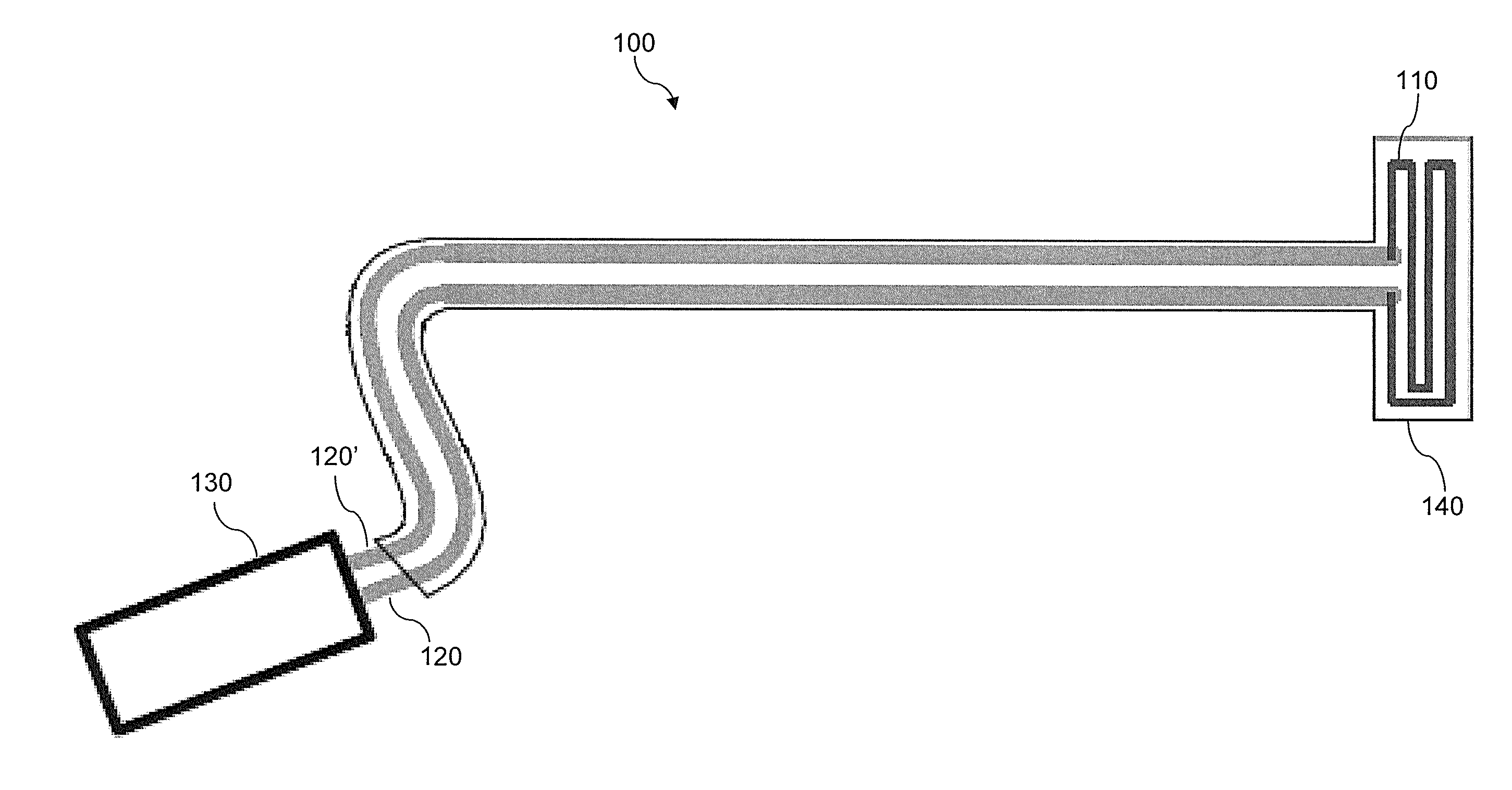
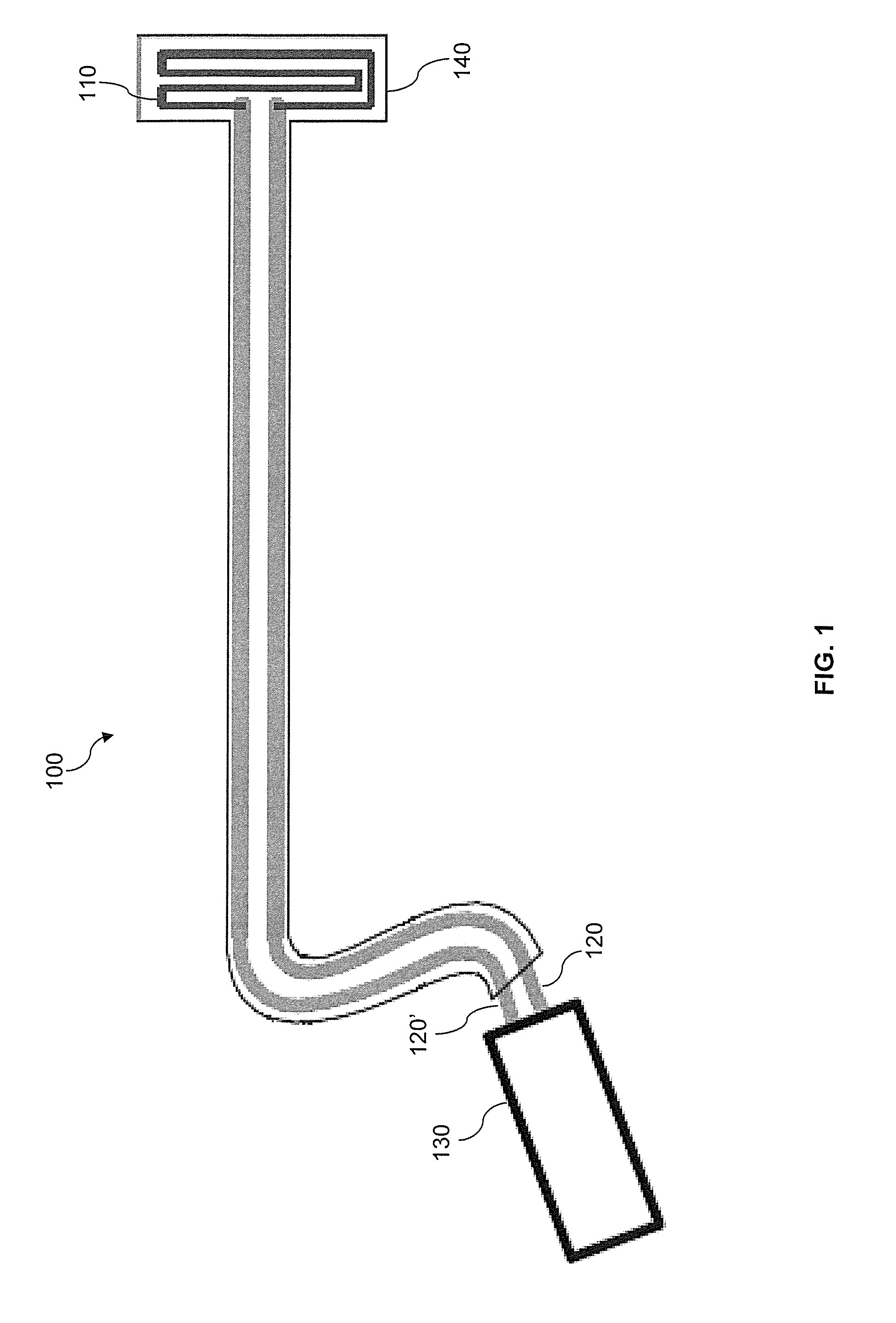
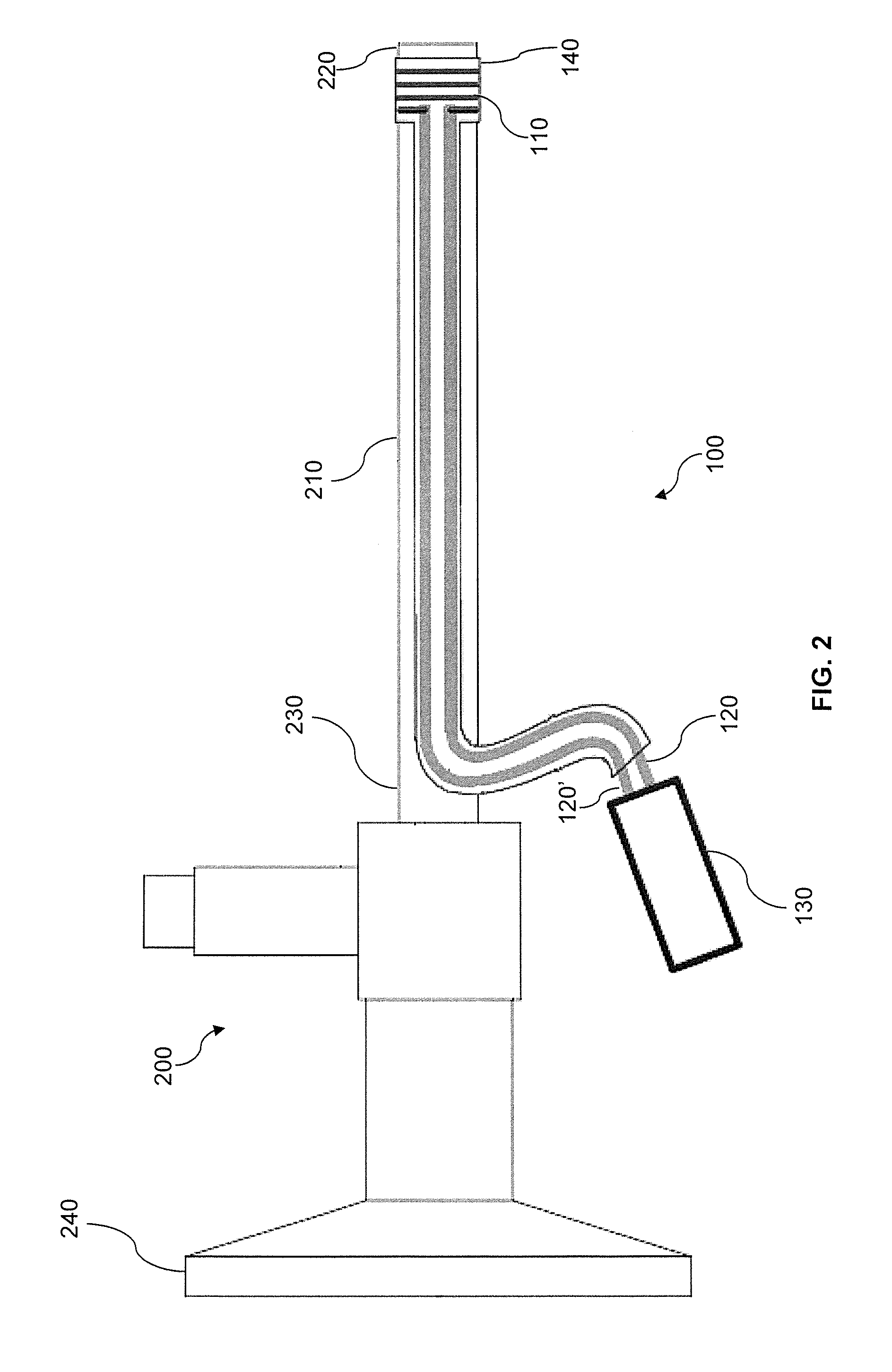
[0033]FIG. 1 illustrates an example endoscope defogging and anti-fogging device 100 according to aspects of the invention.

[0034]Device 100 includes a heating element 110, electrical conductors 120, 120′, power source 130, and insulation 140.

[0035]Heating element 110 may be a wire coil, trace, film, or other suitable structure and may be made from a material which heats when a sufficient current is applied. Suitable materials include Nichrome, Constantan, Carbon, Iron, semiconducting ink, or any other material or alloy commonly used in constructing resistors.

[0036]Electrical conductors 120 and 120′ are wires or traces made from a conducting material suitable for delivering power to resistive heating element 110 while maintaining a reasonably low level of resistive heating and voltage drop within electrical conductors 120 and 120′

[0037]Power source 130 supplies power to the heating element 110 via conductors 120, 120′. Heating element 110 may be self-limiting such that regardless of t...


PUM


Abstract

A system for preventing or removing fogging from and endoscope which includes an endoscope having a distal end and a heating module disposed over the distal end of the endoscope. The heating module may include a heating element arranged as a single-segment heater, or in a series of elongated portions extending circumferentially around the distal end of the endoscope connected by bend portions that are parallel or tangent to a longitudinal axis of the endoscope. The heating module may also be disposed on or adhered to an outside surface of the endoscope, and may include a heating element made from a resistive heating material. The heating module may be provided as a single-use disposable device, and may include an outside surface made from a biocompatible or sterilizable insulating material.

Description

FIELD OF THE INVENTION[0001]The invention relates to endoscopes in general, and more particularly, to preventing or removing fogging on a distal optical lens or window of an endoscope.BACKGROUND OF THE INVENTION[0002]Fogging is a term commonly used to describe the condensation of liquid water droplets on a clear surface, which can scatter light and obscure the transparency of the surface. Fogging of smooth clear surfaces is a common occurrence, and can cause problems in applications where clarity is important, such as in devices which incorporate optical lenses.[0003]Medical instruments incorporating windows or lenses and which are employed within body cavities, such as endoscopes, are particularly prone to fogging. Changes in temperature and pressure which can be caused by the relatively warm and humid environment of a body cavity or by the introduction of insufflation gas at a particular temperature, pressure, and humidity can promote the formation of condensation on the surfaces ...

Claims


Application Information

Patent Timeline
Patent Type & Authority Applications(United States)
IPC IPC(8): A61B1/00
CPCA61B1/00101A61B1/00135A61B1/127A61B1/128G02B23/2492G02B27/0006
Inventor SOLINGEN, SIMON
Owner KARL STORZ ENDOSCOPY AMERICA
Learn More