
Cooling system and electronic apparatus using the same

a technology of electronic equipment and cooling system, applied in the field of cooling system, can solve the problems of air-based cooling apparatus already coming close to a point where its cooling performance is not enough, and cannot typically maintain its performance, so as to improve heat transfer performance, reduce heat generation, and improve heat transfer performance

Inactive Publication Date: 2014-04-03
HITACHI LTD
View PDF13 Cites 34 Cited by
  • Summary
  • Abstract
  • Description
  • Claims
  • Application Information

AI Technical Summary

Benefits of technology

The invention allows for boiling and smooth liquid flow in a coolant, which improves heat transfer performance. This is especially useful in pool boiling where there is a large amount of heat generated and a large amount of coolant liquid is needed to absorb the heat. In this case, the invention ensures smooth liquid flow and improved heat transfer performance.

Problems solved by technology

A semiconductor device, such as a CPU, described above, when its temperature exceeds a predetermined value, cannot typically maintain its performance and may even be damaged in some cases.
Under the circumstances described above, however, an air-based cooling apparatus has already come close to a point where its cooling performance is not enough, and cooling systems based on new methods are therefore desired.

Method used


Image

  • Cooling system and electronic apparatus using the same
  • Cooling system and electronic apparatus using the same
  • Cooling system and electronic apparatus using the same

Examples


embodiment 1

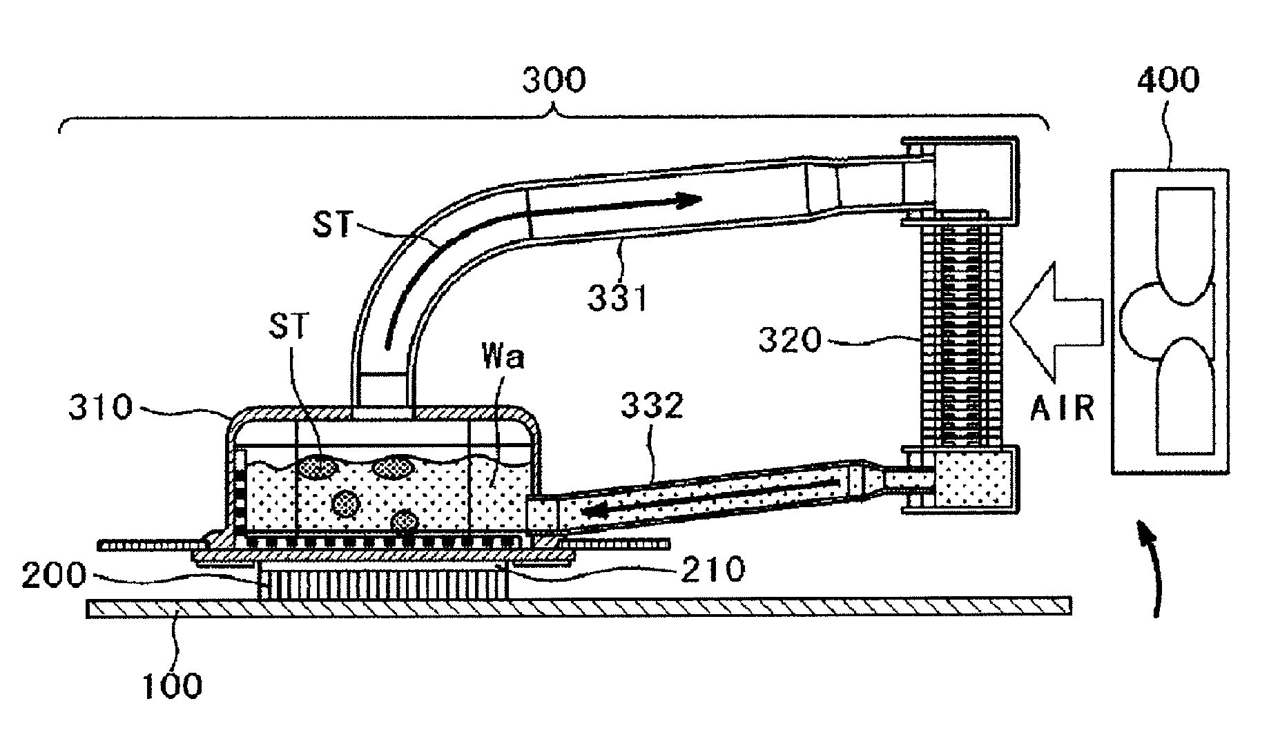
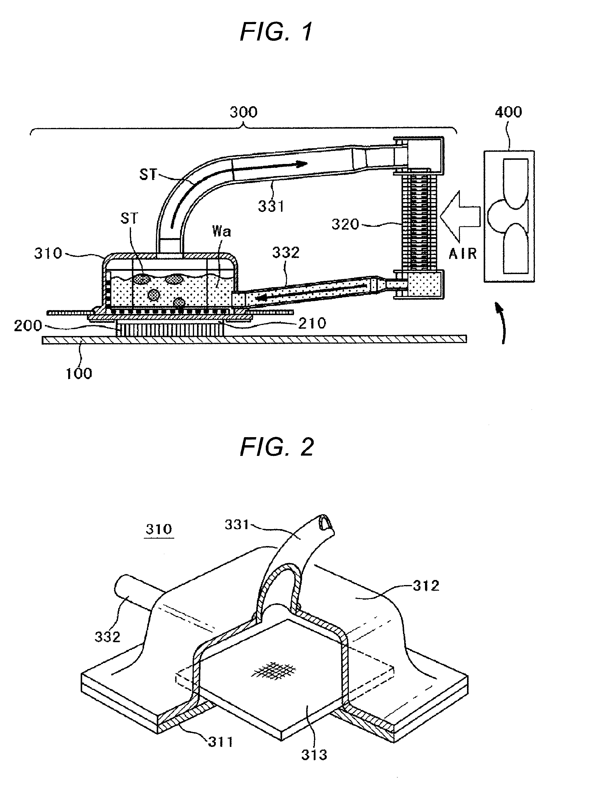
[0027]FIG. 1 shows an overall structure of a cooling system using a thermosiphon. In FIG. 1, a semiconductor device 200, such as a CPU, is mounted as a heat generating source on a surface of a circuit substrate 100. A heat receiving jacket 310, which forms part of a cooling system 300 using a thermosiphon according to the invention, is attached to the front surface of the semiconductor device 200. More specifically, what is called a heat conductive grease 210 is applied onto the front surface of the semiconductor device 200 in order to ensure a satisfactory thermal joint between the semiconductor device 200 and the heat receiving jacket 310, and the heat receiving jacket 310 is fixed with screws (not shown) or any other fixtures to the front surface of the semiconductor device 200 with the front surface of the semiconductor device 200 in contact with the bottom surface of the heat receiving jacket 310. The cooling system 300, the structure of which will be described below in detail,...

embodiment 2

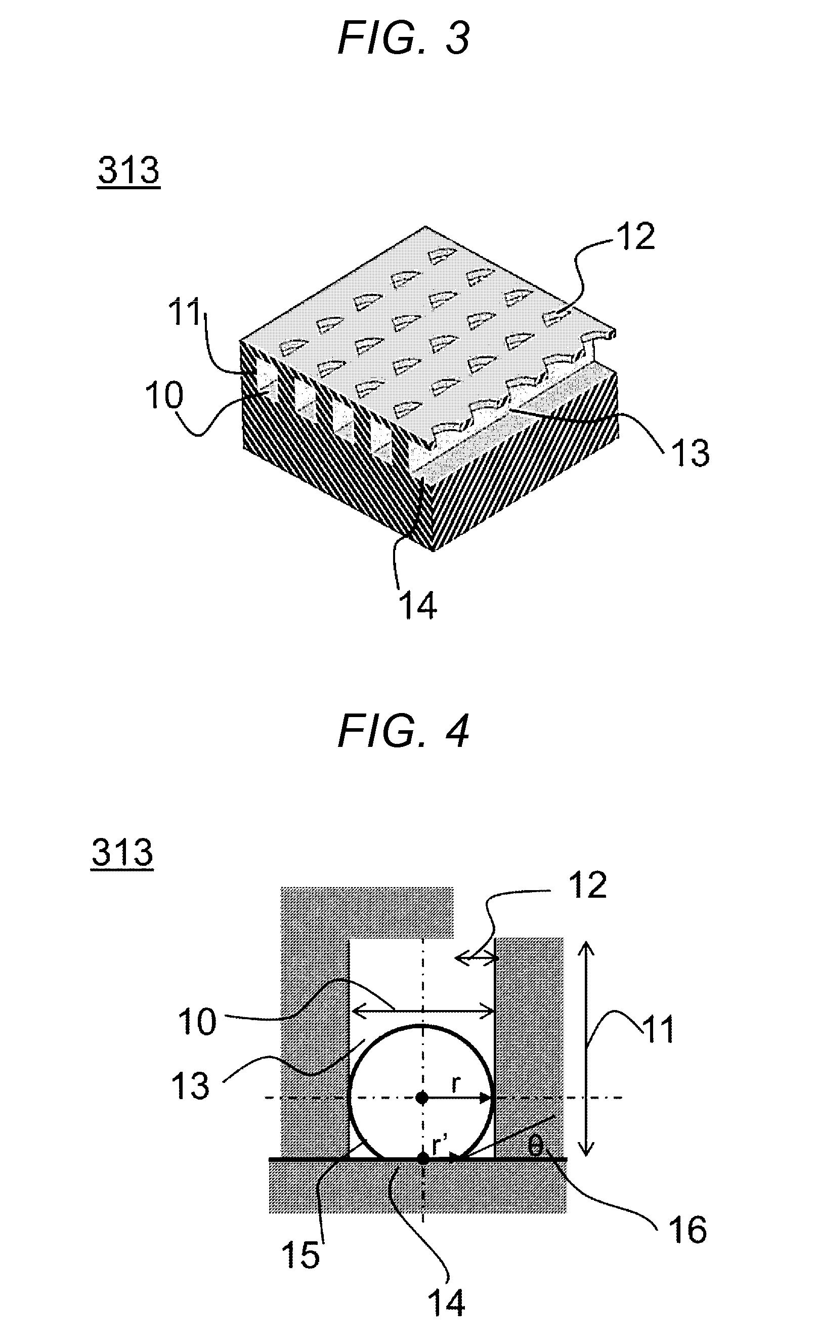
[0043]The fin height of a boiling heat transfer surface will further be described. The shape of a departing steam bubble 15 changes in accordance with the size of the inter-fin gap 10, as shown in FIGS. 5 and 6. FIG. 5 is a cross-sectional view showing a steam bubble generated when the vaporization accelerator plate, which forms the cooling system using a thermosiphon, has a narrow inter-fin gap. In this case, the steam bubble 15 is in contact with the fins and hence has an elongated shape along the space between the fins.

embodiment 3

[0044]On the other hand, FIG. 6 is a cross-sectional view showing a steam bubble generated when the vaporization accelerator plate has a wide inter-fin gap. In this case, the steam bubble 15 departs without touching the fins. In the invention, to improve the heat transfer performance by increasing the fin area, the inter-fin gap 10 is narrowed. That is, Embodiment 3 will be described with reference to the case shown in FIG. 5, in which the inter-fin gap is narrow. The buoyancy of a steam bubble can be expressed as follows in consideration of the balance between the buoyancy and the surface tension of the steam bubble by using a steam bubble volume V, the gravitational acceleration g, the steam density ρv, the liquid density ρl, the radius r′ of the steam bubble 15 to the interface between the steam bubble 15 and the heat transfer surface, the surface tension σ, the contact angle θ, and a surface roughness coefficient K.

V·g·(ρl−σv)=2·π·r′·σ·sin θ·K

where the surface roughness coeffic...


PUM


Abstract

The invention relates to a cooling system and an electronic apparatus using the same, and particularly aims to use a thermosiphon as the cooling system and derives an optimum shape (inter-fin gap, fin height, and fin upper-end hole diameter) of a boiling heat transfer surface for different coolants. In a cooling system using a thermosiphon according to the invention, an optimum shape (inter-fin gap, fin height, and fin upper-end hole diameter) of a boiling heat transfer surface of a heat receiving jacket that forms the cooling system is identified based on a critical radius of a steam bubble produced in an overheated liquid and the diameter of an air bubble departing from the heat transfer surface for a variety of coolants.

Description

BACKGROUND OF THE INVENTION[0001]1. Field of the Invention[0002]The present invention relates to a cooling system for an electronic apparatus in which an enclosure thereof accommodates a plurality of heat generating sources, such as CPUs, and an electronic apparatus using the cooling system.[0003]2. Related Art[0004]In recent years, in an electronic apparatus an representative example of which is a server, what is called a semiconductor device, such as a central processing unit (CPU), is mounted on a circuit substrate in multiple positions in order, for example, to improve the processing speed, and the circuit substrate along with a plurality of hard disk drives and other components is accommodated in a box-shaped rack at a high density.[0005]A semiconductor device, such as a CPU, described above, when its temperature exceeds a predetermined value, cannot typically maintain its performance and may even be damaged in some cases. The temperature of the device therefore needs to be con...

Claims


Application Information

Patent Timeline
Patent Type & Authority Applications(United States)
IPC IPC(8): F28D15/02
CPCF28D15/02F28F13/187F28D15/0266H01L23/427H01L2924/0002H01L2924/00
Inventor KONDOU, YOSHIHIROTAKEDA, FUMIOFUJIMOTO, TAKAYUKI
Owner HITACHI LTD
Learn More