

Optical waveguide sheet, edge-lit backlight unit and laptop computer
- Summary
- Abstract
- Description
- Claims
- Application Information
AI Technical Summary
Benefits of technology
Problems solved by technology
Method used
Image

Examples
first embodiment
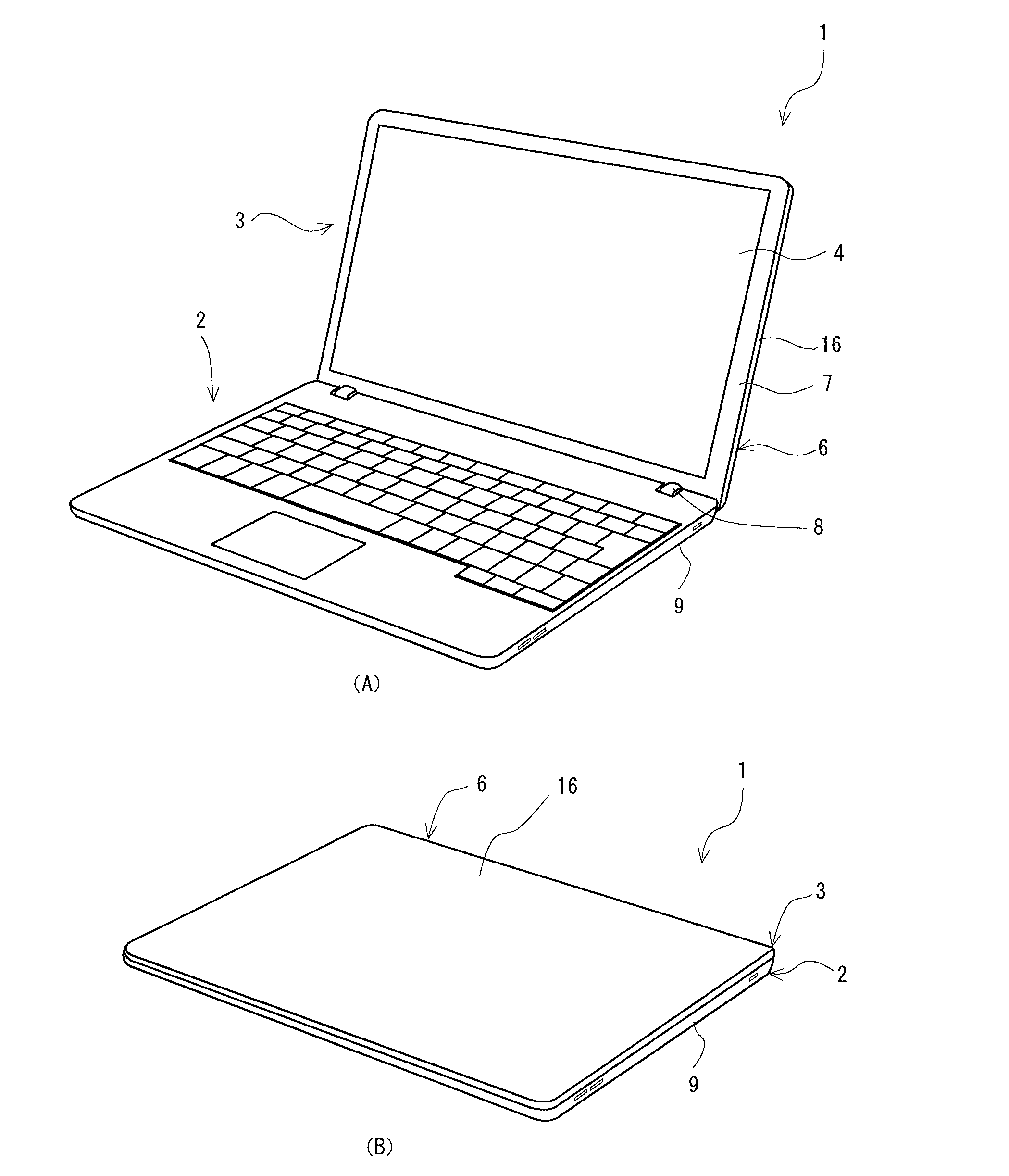
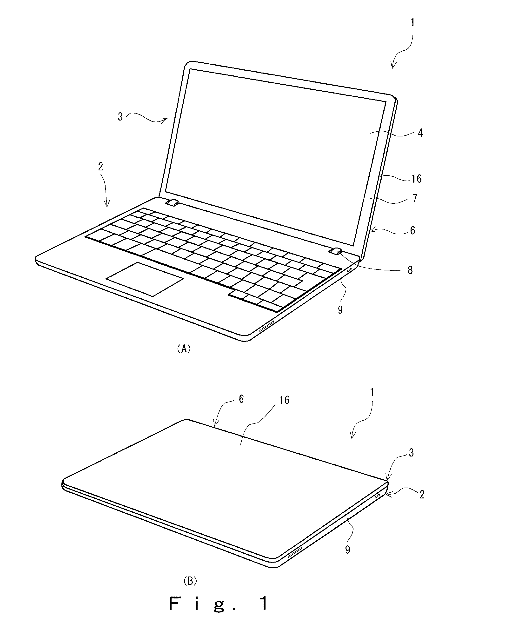
Laptop Computer 1
[0038]A laptop computer 1 shown in FIG. 1 includes an operation unit 2, and a liquid crystal display unit 3 rotatably (enabling to be opened / closed) attached to the operation unit 2. The laptop computer 1 has a housing thickness (at the thickest part (when the liquid crystal display unit 3 is closed)) of no greater than 21 mm, and is generally referred to as Ultrabook (registered trademark) (hereinafter, may be also referred to as “ultraslim computer 1”).
[0039]The liquid crystal display unit 3 of the ultraslim computer 1 includes a liquid crystal panel 4, and an edge-lit backlight unit 11 (hereinafter, may be also referred to as “backlight unit 11”) that directs rays of light from the back face side toward the liquid crystal panel 4. The liquid crystal panel 4 is held at the back face, the lateral face and a circumference of the front face by a casing for a liquid crystal display unit 6 of the housing. In this embodiment, the casing for a liquid crystal display unit...
second embodiment
Optical Waveguide Sheet 21
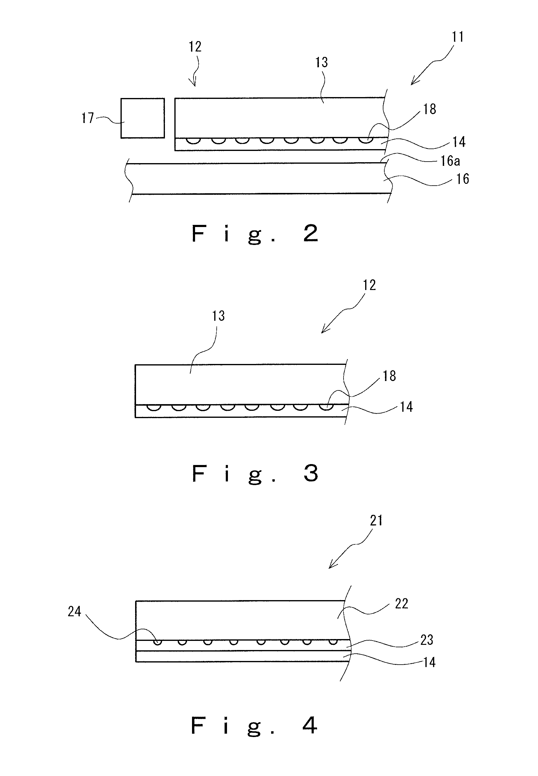
[0079]The optical waveguide sheet 21 shown in FIG. 4 is for use in an edge-lit backlight unit of a liquid crystal display unit of a laptop computer having a housing thickness of no greater than 21 mm in place of the optical waveguide sheet 12 according to the first embodiment. The optical waveguide sheet 21 is a sheet having a three-layer structure composed of an optical waveguide layer 22, a lower refractive index layer 23 laminated on the back face of the optical waveguide layer 22, and a hard coat layer 14 laminated on the back face of the lower refractive index layer 23. Since the hard coat layer 14 is identical to the hard coat layer 14 in FIG. 3, the hard coat layer according to this embodiment is designated using the same number as the hard coat layer in FIG. 3 and explanation thereof will be omitted. The optical waveguide sheet 21 is formed into plate (non-wedge shape) that is in a substantially square shape in a planar view, and has a substantially...
PUM
 Abstract
Description
Claims
Application Information