Circuits and Methods of a Self-Timed High Speed SRAM

a high-speed sram and circuit technology, applied in the direction of information storage, static storage, digital storage, etc., can solve the problems of short propagation delay, inability to generate control signals, waste of excess power, etc., to save power, enhance the driving capability of the reference cell, and save the same device size, area, shape and structure

Active Publication Date: 2014-04-03
ATTOPSEMI TECH CO LTD
View PDF3 Cites 39 Cited by
  • Summary
  • Abstract
  • Description
  • Claims
  • Application Information

AI Technical Summary

Benefits of technology

[0016]Circuits and methods for precisely self-timed SRAM memory are disclosed to track the wordline and / or bitline / bitline bar (BL / BLB) propagation delays. At least one reference cell can be placed near the far end of a driver to drive a selected wordline or a reference wordline. When a wordline and / or a reference wordline is turned on, the reference cell can be selected not earlier than any selected SRAM cells and can activate a reference bitline (RBL) not later than any selected SRAM cells activating the BL or BLB. The activation of the RBL can be used to trigger at least one sense amplifier. The RBL can also be used to de-select wordline or reference wordline after the sense amplifier operation is complete to save power. The reference cell can have substantially the same device size, area, shape, and structure as a normal SRAM cell, but has a bitline in (BLin) coupled to the input of an inverter and the reference bitline (RBL) coupled to the output of the inverter. The BLin and RBL are similar to BL and BLB of an SRAM cell, respectively. The driving capability of the reference cell can be enhanced by enlarging the size of the inverter in a single reference cell or by combining the inverter outputs in a plurality of reference cells with proper setting in BLIns. The setting can be stored in registers for loading.

Problems solved by technology

In such short period of time, it would be very hard to generate control signals to keep propagation delay short while keeping inactive block idle to meet both high speed and low power.
If a WL is turned on too early, excess power may be wasted.
If Twlp is too wide, excess power may be wasted.
Consequently, wide timing margins are needed to build a robust SRAM; otherwise yield and reliable operations may suffer.
If the second timing is not well met, the selected WL may be turned off prematurely even before an SA is activated.
In either case, the SA may sense cell data incorrectly.

Method used


Image

  • Circuits and Methods of a Self-Timed High Speed SRAM
  • Circuits and Methods of a Self-Timed High Speed SRAM
  • Circuits and Methods of a Self-Timed High Speed SRAM

Examples


Embodiment Construction

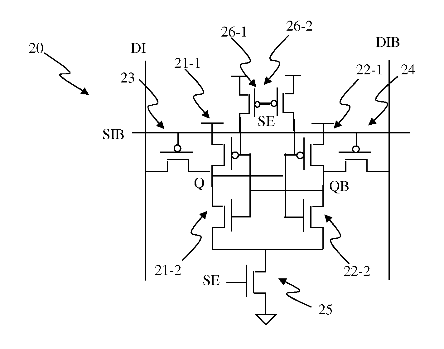
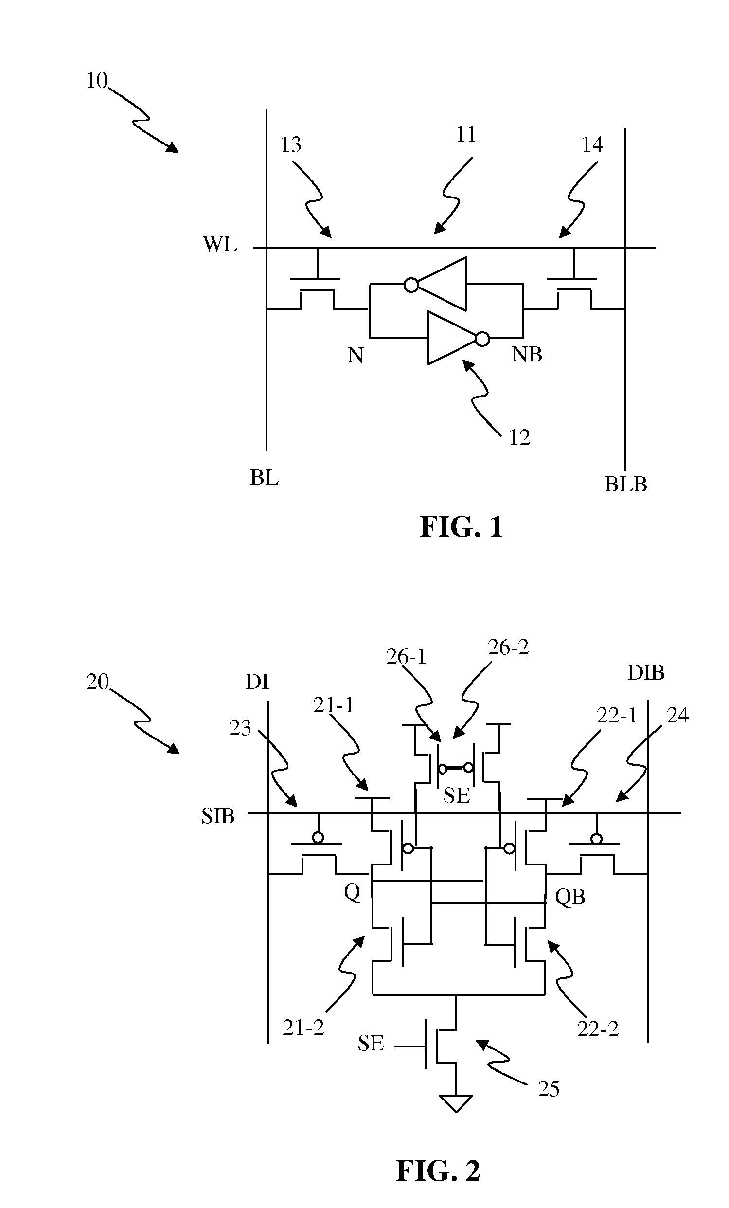
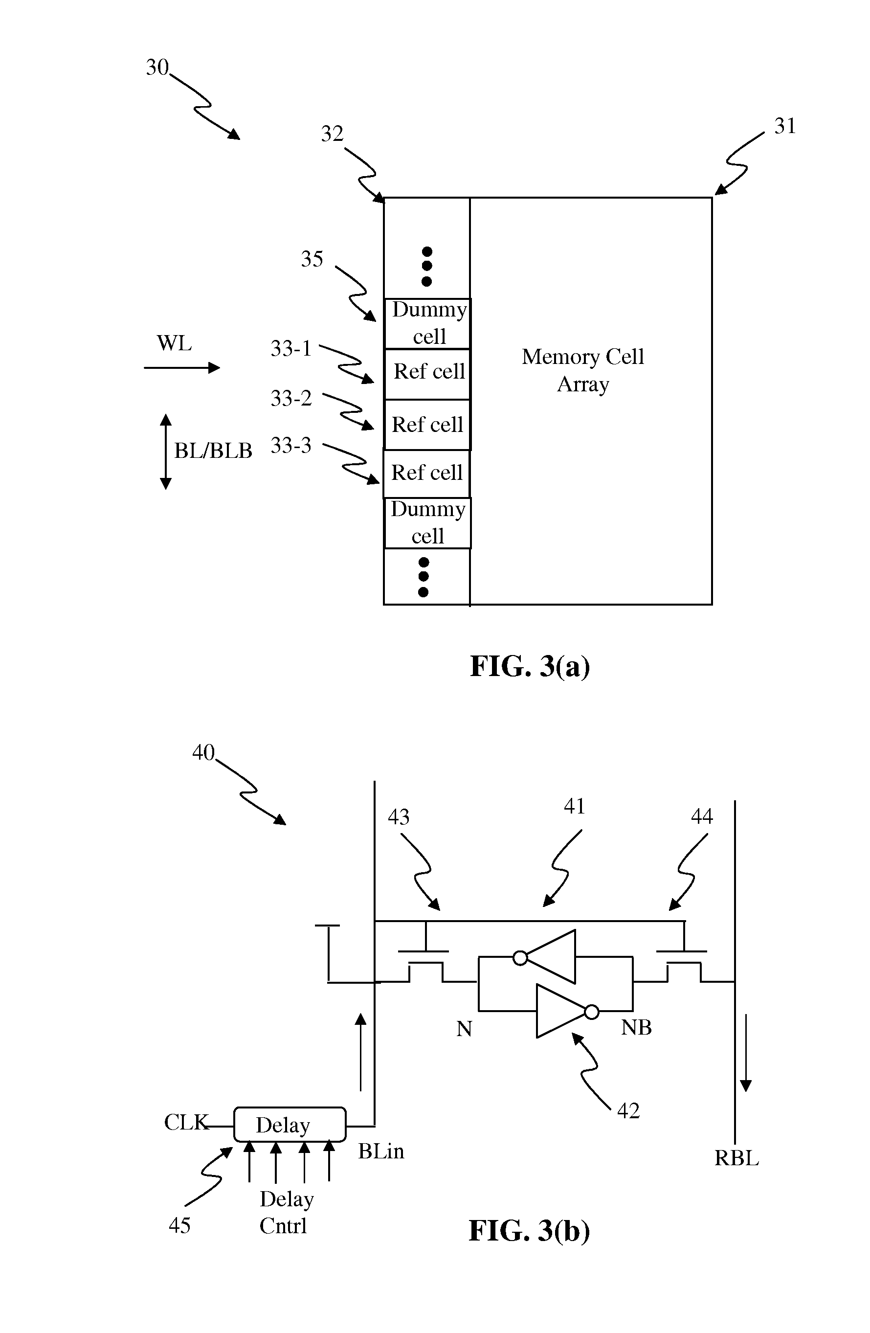
[0038]Embodiments disclosed herein can track wordline and / or bitline delays to activate at least one sense amplifier (SA) and to turn off a wordline after at least one sense amplifier (SA) is activated. A latch-type of SA is essential in today's nanometer SRAM for low power and low voltage operations. However, the latch-type of SA requires sufficient signal splits developed in the input of an SA before being activated; otherwise irrevocable incorrect data can be sensed and latched. Without sufficient timing margins, the input signals may not be split wide enough for sensing. On the other hand, if the timing margins are too wide, the speed of an SRAM can suffer. Advantageously, embodiments disclosed herein are capably of tracking critical timings to achieve reliable operations and yet high speed by using at least one reference cell, similar to the normal cell, to track wordline and / or bitline delay and to turn on at least one sense amplifier accordingly. After the SA is activated, th...


PUM


Abstract

Circuits and methods for precisely self-timed SRAM memory are disclosed to track the wordline and/or bitline/bitline bar (BL/BLB) propagation delays. At least one reference cell can be placed near the far end of a driver to drive a selected wordline or a reference wordline. When a wordline and/or a reference wordline is turned on, the reference cell can be selected not earlier than any selected SRAM cells and can activate a reference bitline (RBL) not later than any selected SRAM cells activating the BL or BLB. The activation of the RBL can be used to trigger at least one sense amplifier. The RBL can also be used to de-select wordline or reference wordline after the sense amplifier operation is complete to save power.

Description

CROSS-REFERENCE TO RELATED APPLICATIONS[0001]This application claims priority of U.S. provisional Patent Application No. 61 / 708,040, filed on Sep. 30, 2012 and entitled “Circuits and Methods of A Self-Timed High Speed SRAM,” which is hereby incorporated herein by reference.BACKGROUND OF THE INVENTION[0002]1. Field of the Invention[0003]The present invention relates to effective circuit, system designs, and methods of a self-timed SRAM for high speed and low power applications.[0004]2. Description of the Related Art[0005]Today's SRAM is commonly used as caches in ultra-high clock-rate CPU. A clock rate of 1 GHz CPU can be achieved easily in today's nanometer devices, such as 65 nm CMOS and beyond. For an SRAM to match such high clock rate, the access time needs to be less than 1 ns. In such short period of time, it would be very hard to generate control signals to keep propagation delay short while keeping inactive block idle to meet both high speed and low power. It is the objective...

Claims


Application Information

Patent Timeline
Patent Type & Authority Applications(United States)
IPC IPC(8): G11C7/06
CPCG11C7/065G11C7/227G11C11/418G11C11/419
Inventor CHUNG, SHINE C.
Owner ATTOPSEMI TECH CO LTD
Why Eureka
Try Eureka