Turbine-Driven Reciprocating Compressor and Method

a reciprocating compressor and turbine technology, applied in the direction of positive displacement liquid engine, pump control, pump pump, etc., can solve the problems of high wear rate, non-uniform temperature field inside the turbine, and high risk of damage to the steam turbine shaft and seal, so as to increase the speed of the turbine

Inactive Publication Date: 2014-04-03
NUOVO PIGNONE SPA
View PDF6 Cites 11 Cited by
  • Summary
  • Abstract
  • Description
  • Claims
  • Application Information

AI Technical Summary

Benefits of technology

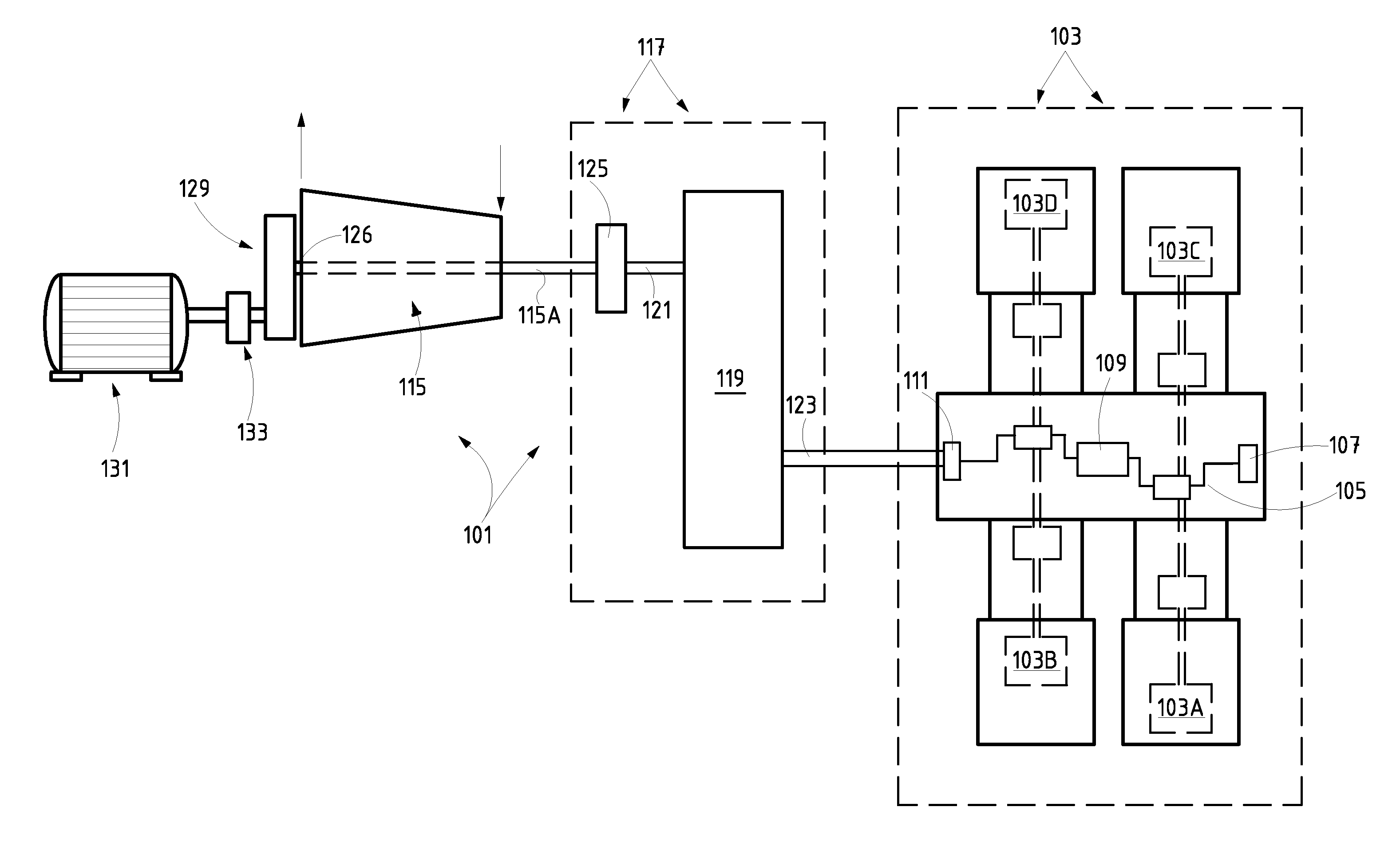
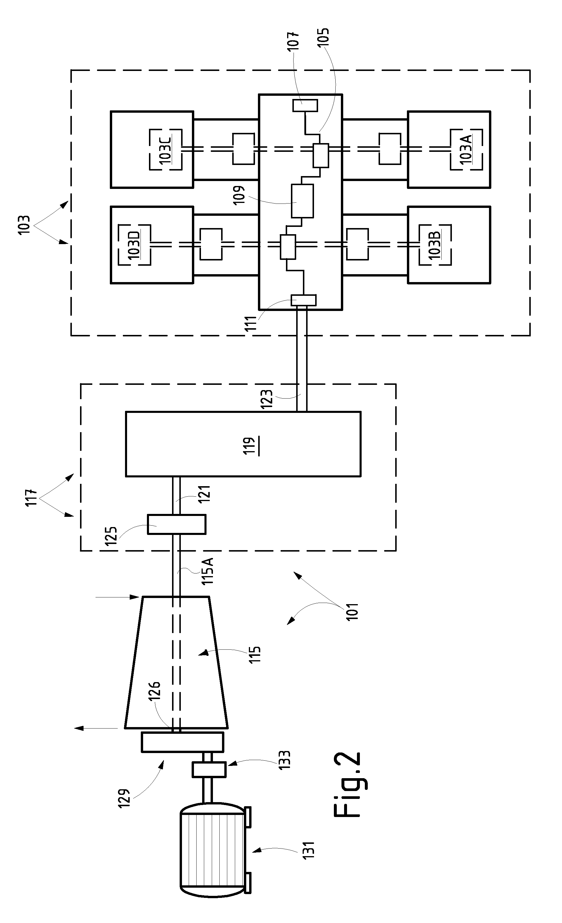
[0013]According to one embodiment, a reciprocating compressor system is provided, comprising a turbine and at least one reciprocating compressor driven by the turbine. In some embodiments the turbine is a steam turbine. A gearbox can be provided in the system and is arranged between the turbine and the reciprocating compressor. A clutch is provided, between the turbine and the reciprocating compressor, for mechanically disconnecting the turbine from the reciprocating compressor during a transient phase of operation of the system, for example during a barring phase or during a turbine warm-up phase. A barring device is further provided for slow-turning the turbine during a barring phase.
[0015]The clutch can be disengaged for example upon shutdown of the turbine. The reciprocating compressor remains then stationary while the turbine is slow-turned at a barring rotary speed, to prevent bowing of the turbine rotor during cooling. The barring speed can be set at a very low value, since failures of the reciprocating compressor bearings due to insufficient rotary speed of the hydrodynamic bearings will not occur, as the reciprocating compressor is inoperative. The barring device can thus be designed to provide limited power, thus reducing the costs and dimension of the barring device.
[0025]In other embodiments, at shutdown of the turbine, the reciprocating compressor can be maintained in operative conditions by driving the reciprocating compressor with a second mover.
[0026]According to further embodiments, a method is provided, comprising the steps of starting the turbine while the turbine is disengaged from the gearbox and the reciprocating compressor; increasing the speed of the turbine above at least one critical rotary speed of the shaft line; engaging the turbine to the gearbox and the reciprocating compressor, starting operation of the reciprocating compressor.
[0027]According to yet further embodiments, a method is provided, comprising the steps of starting the reciprocating compressor by means of a secondary mover at a rated speed; starting the turbine while the turbine is disengaged from the gearbox and the reciprocating compressor; warming up the turbine rotating the turbine at a speed lower than a minimum rated speed; increasing the speed of the turbine; engaging the turbine to the gearbox and the reciprocating compressor; deactivating the secondary mover.

Problems solved by technology

Non-uniform temperature fields inside the turbine arise upon shutdown, since the lower portions of the turbine cool faster than the upper portions.
Moreover, the barring speed is insufficient to develop a lubrication oil film in the hydrodynamic bearings, and therefore during slow turning of the turbine the bearings operate in a boundary lubrication condition involving high wear rate.
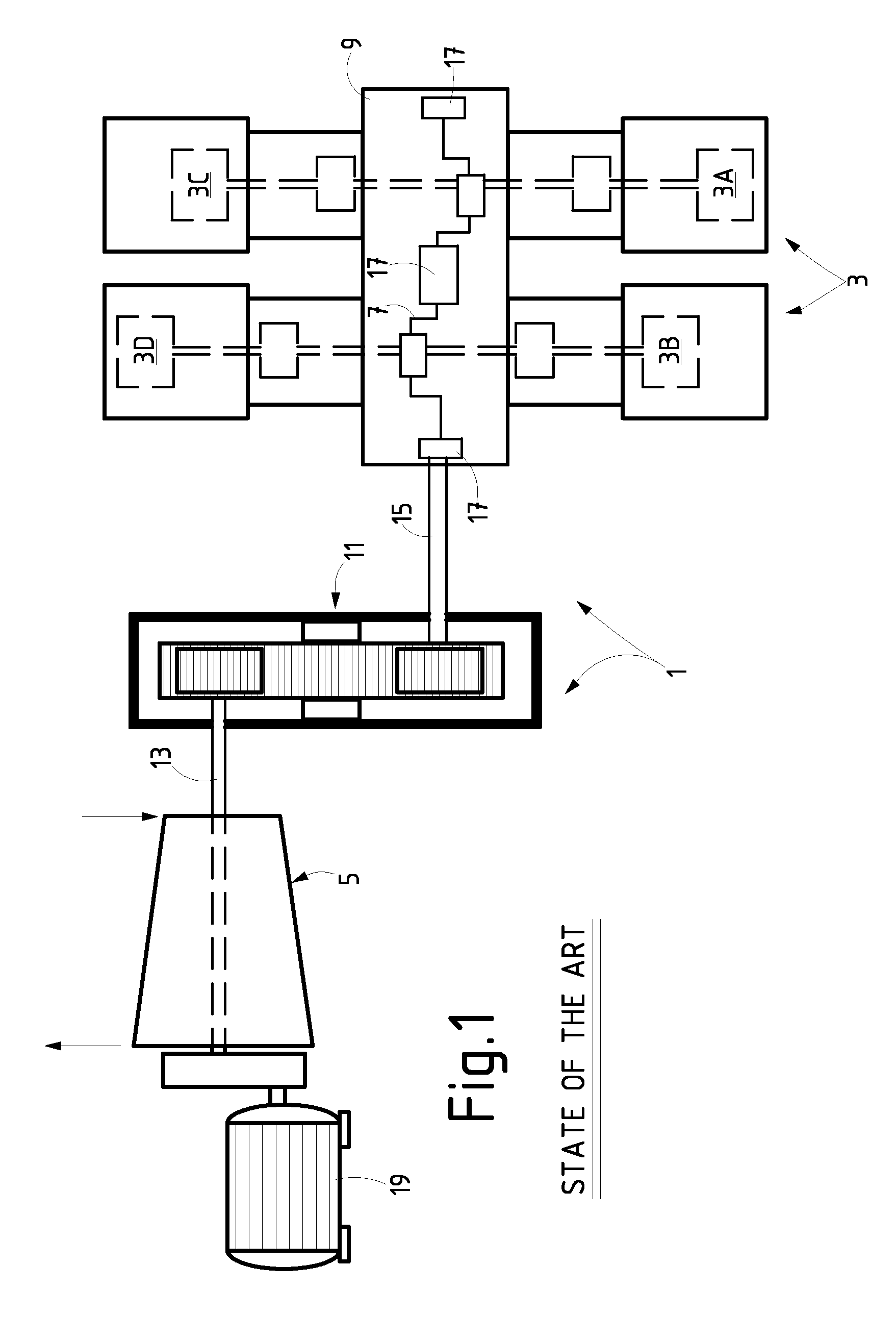
Furthermore, in case of sudden failure of the reciprocating compressor 3, there is a risk of damage of the steam turbine shaft and seals, if the barring device 19 is not able to run, e.g. in case of locking of the crankshaft 7.
This can provoke resonance phenomena, which can damage components of the system, including the gearbox.
During this transient phase, the turbine cannot generate sufficient power to drive the reciprocating compressor under load.
On the other hand, the reciprocating compressor cannot run under no-load conditions for a long period of time.

Method used


Image

  • Turbine-Driven Reciprocating Compressor and Method
  • Turbine-Driven Reciprocating Compressor and Method
  • Turbine-Driven Reciprocating Compressor and Method

Examples


Embodiment Construction

[0035]The following detailed description of the embodiments refers to the accompanying drawings. The same reference numbers in different drawings identify the same or similar elements. Additionally, the drawings are not necessarily drawn to scale. Also, the following detailed description does not limit the invention. Instead, the scope of the invention is defined by the appended claims.

[0036]Reference throughout the specification to “one embodiment” or “an embodiment” or “some embodiments” means that the particular feature, structure or characteristic described in connection with an embodiment is included in at least one embodiment of the subject matter disclosed. Thus, the appearance of the phrase “in one embodiment” or “in an embodiment” or “in some embodiments” in various places throughout the specification is not necessarily referring to the same embodiment(s). Further, the particular features, structures or characteristics may be combined in any suitable manner in one or more e...


PUM


Abstract

A reciprocating compressor system is provided comprising: a turbine; a reciprocating compressor driven by the turbine; and a gearbox arranged between the turbine and the reciprocating compressor. The turbine is provided with a barring device arranged for slow-turning the turbine during a barring phase. A clutch is arranged between the turbine and the reciprocating compressor, for mechanically disconnecting the turbine from the reciprocating compressor during a transient phase of operation of the system.

Description

BACKGROUND OF THE INVENTION[0001]Embodiments of the present disclosure generally relate to reciprocating compressor systems and more specifically to reciprocating compressor systems driven by turbines, such as steam turbines.[0002]Reciprocating compressors are commonly used in the industry for compressing gases in a wide range of applications. Reciprocating compressors are usually driven by a prime mover, which can be an electric motor, a reciprocating internal combustion engine or a gas or steam turbine.[0003]FIG. 1 illustrates an arrangement 1 comprising a reciprocating compressor system, comprising a compressor 3, and a steam turbine 5 used to drive the reciprocating compressor 3. In FIG. 1 the reciprocating compressor 3 comprises a plurality of compressor cylinders 3A, 3B, 3C and 3D. A common crankshaft 7 drives the four reciprocating compressor cylinders 3A-3D and supports a flywheel (not shown). The crankshaft 7 is rotatingly supported in a casing 9 and is driven into rotation...

Claims


Application Information

Patent Timeline
Patent Type & Authority Applications(United States)
IPC IPC(8): F04B35/00
CPCF04B35/00F01D15/08F01D15/12F04B35/006F04B35/01F02C7/36
Inventor PRATELLI, GUIDOTOGNARELLI, LEONARDO LIMILANI, GIULIANOFAILLA, LORENZOTAMMARO, NICOLASONNOLI, MARCO
Owner NUOVO PIGNONE SPA
Why Eureka
Try Eureka