Recirculation Unit For a Fuel Cell System

a fuel cell and recirculation unit technology, applied in the direction of fuel cells, liquid degasification regulation/control, electrical devices, etc., can solve the problems of reducing hydrogen concentration, level sensors, and pronounced tendency to contamination, and achieves simple and cost-effective design, easy and cost-effective realization and implementation, and minimize repairs and services.

Inactive Publication Date: 2014-04-03
DAIMLER AG
View PDF3 Cites 5 Cited by
  • Summary
  • Abstract
  • Description
  • Claims
  • Application Information

AI Technical Summary

Benefits of technology

[0008]Another option for improving the switching of the discharge valve is to predict the resulting quantity of water by determining in advance and adding the quantity of water produced in the anode region for the particular power that is present. As soon as an appropriate quantity of water has accumulated in the circuit of the recirculation device the discharge valve is then opened for a period corresponding to this quantity of water. This improves the functionality compared to opening of the discharge valve in a strictly time-controlled manner. However, fluctuations and inaccuracies are still present, so that here as well, more hydrogen is lost than is desired, since for the same reasons as described above, a certain safety margin in the opening time must always be maintained so that in any case, all of the water is discharged from the region of the recirculation device.
[0012]Exemplary embodiments of the present invention are directed to a recirculation device for a fuel cell system that operates securely and reliably and that has a simple and efficient design. Exemplary embodiments of the present invention are also directed to a method for discharging liquid and / or gases from such a recirculation device, which minimizes the losses of hydrogen.
[0013]The recirculation device according to exemplary embodiments of the invention for a fuel cell system necessarily includes a recirculation line connecting the outlet of the anode region of the fuel cell to the inlet thereof. A liquid separator is situated in the area of this recirculation line, and has a discharge line having a discharge valve for liquid and / or gas. According to the invention, a bubble sensor for controlling the discharge valve is situated in the area of the discharge line. By use of such a bubble sensor, a distinction may be easily and very efficiently made between liquid flowing in the discharge line and gas flowing in the discharge line. The boundary between the flowing liquid and the gas following same may thus be recognized and detected using such a bubble sensor, and may be used for controlling the discharge valve. The sensor may in particular have a contactless design, preferably as an ultrasonic sensor, an optical sensor, or the like. A bubble sensor of this type having high reliability and high resolution is available on the market at low cost, so that a simple, reliable, and cost-effective implementation of the recirculation device for the fuel cell system is possible.
[0015]As previously mentioned, the bubble sensor may preferably be designed as a contactless bubble sensor. This results in a simple and efficient design, which is very favorable with regard to contamination because the bubble sensor typically surrounds the discharge line only from the outside, and therefore does not come into contact with the medium flowing in the discharge line. Contamination via this medium is thus ruled out, and without this contamination the bubble sensor functions securely and reliably, unlike the capacitive filling level sensors known from the prior art, which are situated in the volumetric flow.
[0020]The recirculation device according to the invention as well as the method for discharging liquid and / or gases are very efficient, reliable, and easy and cost-effective to realize and implement. The recirculation device and the method are therefore particularly suited for use in fuel cell systems which generate electrical power, in particular for drive purposes, in a motor vehicle.
[0021]In particular for vehicle applications and the associated unit quantities, the simple and cost-effective design is extremely important. Likewise, reliable functionality is crucial in order to minimize repairs and service and to be able to achieve the longest possible maintenance intervals for the motor vehicles.

Problems solved by technology

The inert gases, in particular nitrogen, which diffuse from the cathode region into the anode region through the membranes of the fuel cell accumulate in the recirculation device over time, resulting in a drop in the hydrogen concentration.
It has now been shown that the filling level sensors, which typically have a capacitive design, have a pronounced tendency toward contamination, as the result of which their functionality is very unreliable.
When strictly time control is used, this frequently results in problems due to excessive water in the circuit of the recirculation device.
Since liquid water may block the active surface of the anode region when it penetrates into the anode region, this is very disadvantageous for the performance of the fuel cell.
In part load operation, however, the time periods are then so long that a comparatively large quantity of hydrogen is also lost, which is undesirable.
However, fluctuations and inaccuracies are still present, so that here as well, more hydrogen is lost than is desired, since for the same reasons as described above, a certain safety margin in the opening time must always be maintained so that in any case, all of the water is discharged from the region of the recirculation device.
However, these are comparatively complex and costly, and susceptible to malfunction.
When hydrogen arrives in the region of the cathode, this results in a voltage dip in the fuel cell, which is particularly apparent in part load operation.
This method also has the major disadvantage that significantly more hydrogen is lost than is necessary, since the hydrogen must first overcome the line length between the discharge valve and the cathode region, and only then can it be detected.
Thus, the hydrogen present in this line length invariably goes to waste during each discharge operation.

Method used


Image

  • Recirculation Unit For a Fuel Cell System
  • Recirculation Unit For a Fuel Cell System

Examples


Embodiment Construction

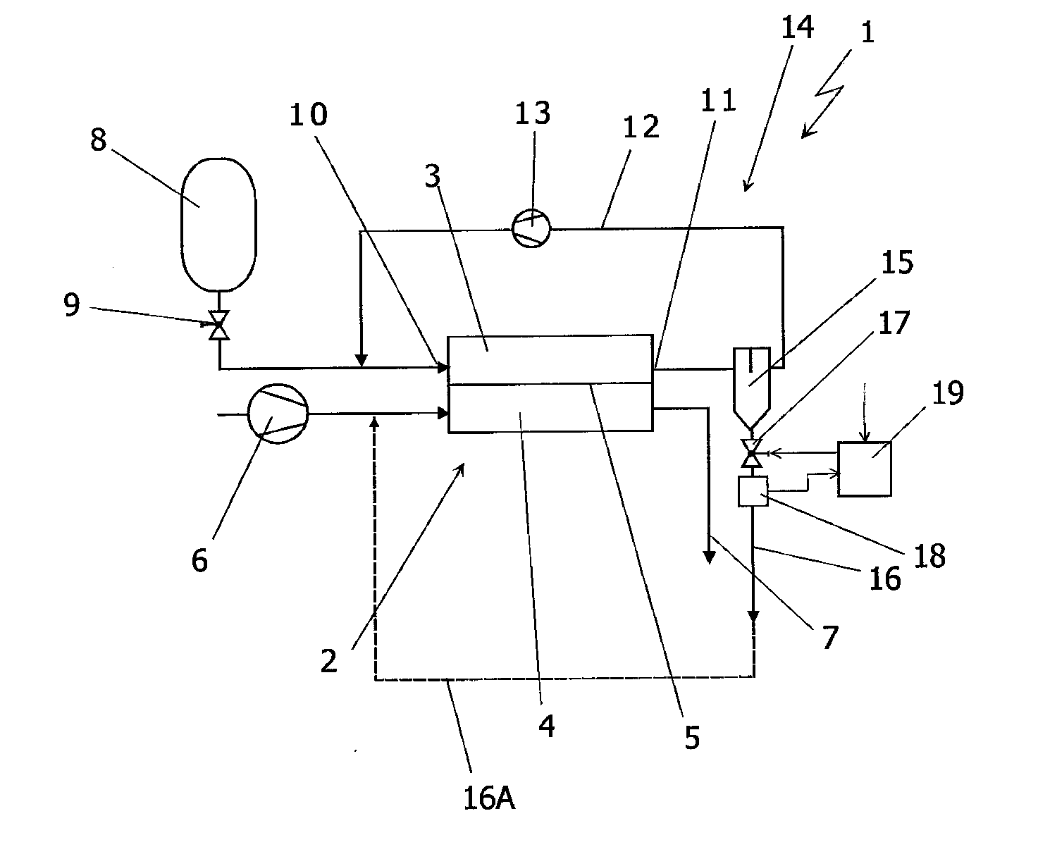
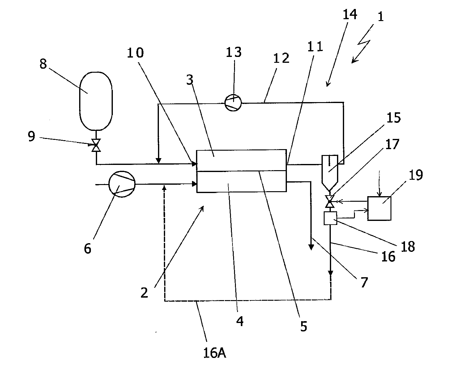
[0024]The sole FIGURE schematically illustrates a fuel cell system 1. The core of this fuel cell system 1 is a fuel cell 2, which is designed as a stack of individual fuel cells, referred to as a so-called fuel cell stack. The fuel cell 2 includes an anode region 3 and a cathode region 4 separated from one another by a proton-conducting membrane 5. The fuel cell 2 is accordingly a PEM fuel cell. The cathode region 4 of the fuel cell 2 is supplied, via an air conveying device 6, with filtered air as an oxygen-containing medium. Spent exhaust air passes from the fuel cell system 1 via an exhaust air line 7. The exhaust air may be discharged to the environment, expanded through a turbine, and / or supplied to combustion. However, this is not significant for the invention.

[0025]The anode region 3 of the fuel cell 2 is supplied with hydrogen from a compressed gas store 8 via a valve and pressure regulation device 9. The fresh hydrogen flows through a supply line to the inlet 10 of the anod...


PUM

PropertyMeasurementUnit
areaaaaaaaaaaa
timeaaaaaaaaaa
distanceaaaaaaaaaa

Abstract

A recirculation device for a fuel cell system includes a recirculation line connecting the outlet and inlet of the anode region of the fuel cell. The recirculation device includes a liquid separator situated in the area of the recirculation line and a discharge line having a discharge valve for liquid and / or gases. A bubble sensor for controlling the discharge valve is situated in the area of the discharge line. A method for discharging liquid and / or gases from a recirculation device opens and closes the discharge valve as a function of an event detected by the bubble sensor.

Description

BACKGROUND AND SUMMARY OF THE INVENTION[0001]Exemplary embodiments of the present invention relate to a recirculation device for a fuel cell system.[0002]Fuel cell systems operated with gaseous starting products, for example air and hydrogen or hydrogen-containing gas, are known from the general prior art. They generally have at least one fuel cell with an anode region and a cathode region. The fuel cell is typically designed as a stack of individual fuel cells, and is referred to as a fuel cell stack. In fuel cells of this type, in particular those designed in PEM technology, the exhaust gas from the anode region is often collected and resupplied, together with fresh gas, in particular fresh hydrogen, to the anode region. A recirculation device is necessary for this purpose.[0003]This type of recirculation device is described using name “fuel circuit” in PCT Publication No. WO 2008 / 052578 A1. In this recirculation device, exhaust gas from the anode region of the fuel cell is led th...

Claims


Application Information

Patent Timeline
Patent Type & Authority Applications(United States)
IPC IPC(8): H01M8/04
CPCH01M8/04097B01D19/0063H01M8/04164H01M8/04843Y02E60/50
Inventor MUETSCHELE, ARMIN
Owner DAIMLER AG
Why Eureka
Try Eureka