
Fluid control in reservoir fluid samplilng tools

a reservoir fluid and fluid control technology, applied in the field of oil and gas reservoir technology, can solve the problems of increasing the time and difficulty of making tests and taking samples, and affecting the accuracy of results

Inactive Publication Date: 2014-04-10
HALLIBURTON ENERGY SERVICES INC
View PDF0 Cites 19 Cited by
  • Summary
  • Abstract
  • Description
  • Claims
  • Application Information

AI Technical Summary

Benefits of technology

This solution enables precise control of fluid phases, optimizing pumping speeds while preventing contamination, resulting in more accurate and efficient reservoir fluid sampling that closely represents formation fluid properties.

Problems solved by technology

In such testing or sampling, many problems can arise.
Further, information concerning many properties of the fluid must be obtained, and determination of one property may interfere with determination of another property.
However, wells are often deep, which increases the time and difficulty of making tests and taking samples.
These factors often lead to maximizing the pumping speed to save time and related costs.
However, if attention is only paid to maintaining efficient pumping speed, vapor can form in the system, in which case the test or sample is not representative of the reservoir fluid.
On the other hand, slowing or stopping the pumping can result in contamination encroachment into the sample zone, which reduces the accuracy of the results and leads to even longer testing and sampling times. Thus, fluid control during drilling, pumping, and other reservoir operations can be difficult.
In the actual display, these densities are shown in color, but because patent drawings do not yet allow color, the different densities are designated by different shading.
Thus, the prior art system did not maintain the sand face pressure above the bubble point, and the sampling was not representative of the reservoir.
Clearly, the state-of-the-art was not able to control the parameters of the sampling tool satisfactorily in this instance.

Method used


Image

  • Fluid control in reservoir fluid samplilng tools
  • Fluid control in reservoir fluid samplilng tools
  • Fluid control in reservoir fluid samplilng tools

Examples


Embodiment Construction

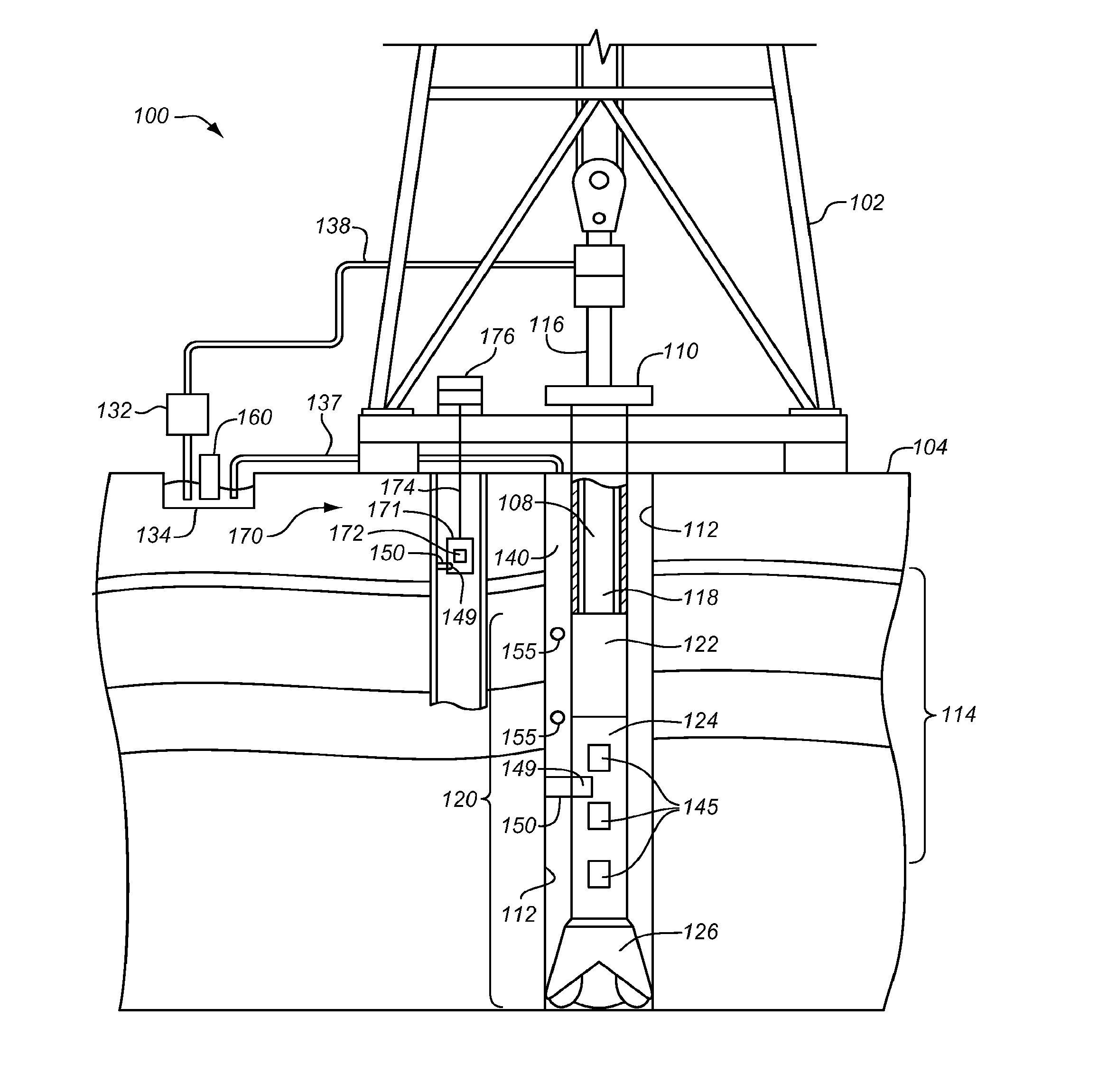
[0021]The invention relates to systems 100, 200 including a downhole tool 124, 150, 204, 205 incorporating a variable check valve 420, 424. Generalized systems according to the invention that may incorporate a downhole tool 124, 150, 204, 205 are shown in FIGS. 4 and 5 to orient the reader. Details of an exemplary tool according to the invention are shown in FIG. 5, and details of another exemplary tool according to the invention are shown in FIG. 9, along with pressure information to illustrate the use of the tool. Details of an exemplary pumping system 220, according to the invention as used in the tool of FIG. 9 are shown in FIG. 6, and examples of a check valve 420, 424 according to the invention as may be used in any of the systems are shown in FIGS. 7 and 8.

[0022]FIG. 4 illustrates a system 100 for drilling or pumping operations according to the invention. It should be noted that the system 100 can also include a system for pumping operations, or other operations. The system 1...


PUM


Abstract

A pumping system includes a probe to suction a fluid from a fluid reservoir, a pump in fluid communication with the probe, and a sensor for detecting phase changes in said pumping system. The sensor is in fluid communication with the probe or pump and is operable to generate a sensor signal. The pumping system also includes a fluid exit from the pumping system that is in fluid communication with said pump, and a variable force check valve that is located between the probe and fluid exit.

Description

CROSS REFERENCE TO RELATED APPLICATION[0001]This application is a Continuation of U.S. patent application Ser. No. 12 / 842,377 filed on Jul. 23, 2010 entitled, “FLUID CONTROL IN RESERVOIR FLUID SAMPLING TOOLS,” which is incorporated herein for all purposes.TECHNICAL FIELD[0002]This invention relates in general to oil and gas reservoir technology, and more particularly to apparatus and methods for controlling the fluid phase in sampling and other pumping operations.BACKGROUND[0003]During drilling, pumping, and similar operations in reservoirs, such as oil and gas reservoirs, it is often useful to test or sample the reservoir fluid. In such testing or sampling, many problems can arise. It is important that the fluid tested or the sample retrieved is representative of the reservoir fluid. Further, information concerning many properties of the fluid must be obtained, and determination of one property may interfere with determination of another property. The various factors of importance ...

Claims


Application Information

Patent Timeline
Patent Type & Authority Applications(United States)
IPC IPC(8): E21B49/08E21B43/12
CPCE21B43/12E21B49/084E21B34/08E21B49/10
Inventor VAN ZUILEKOM, ANTHONY H.PELLETIER, MICHAEL T.GAO, LI
Owner HALLIBURTON ENERGY SERVICES INC
Learn More