Generator dispatching or load shedding control method and system for microgrid applications

a technology for microgrids and generators, applied in process and machine control, greenhouse gas reduction, instruments, etc., can solve the problems of not always ensuring maximum efficiency and not being scalable for relatively large intelligent distributed power generation systems

Active Publication Date: 2014-04-10
EATON INTELLIGENT POWER LTD
View PDF1 Cites 97 Cited by
  • Summary
  • Abstract
  • Description
  • Claims
  • Application Information

AI Technical Summary

Problems solved by technology

However, this approach does not always guarantee maximum efficiency and is not scalable for relatively larger intelligent distributed power generation systems.

Method used


Image

  • Generator dispatching or load shedding control method and system for microgrid applications
  • Generator dispatching or load shedding control method and system for microgrid applications
  • Generator dispatching or load shedding control method and system for microgrid applications

Examples


example 1

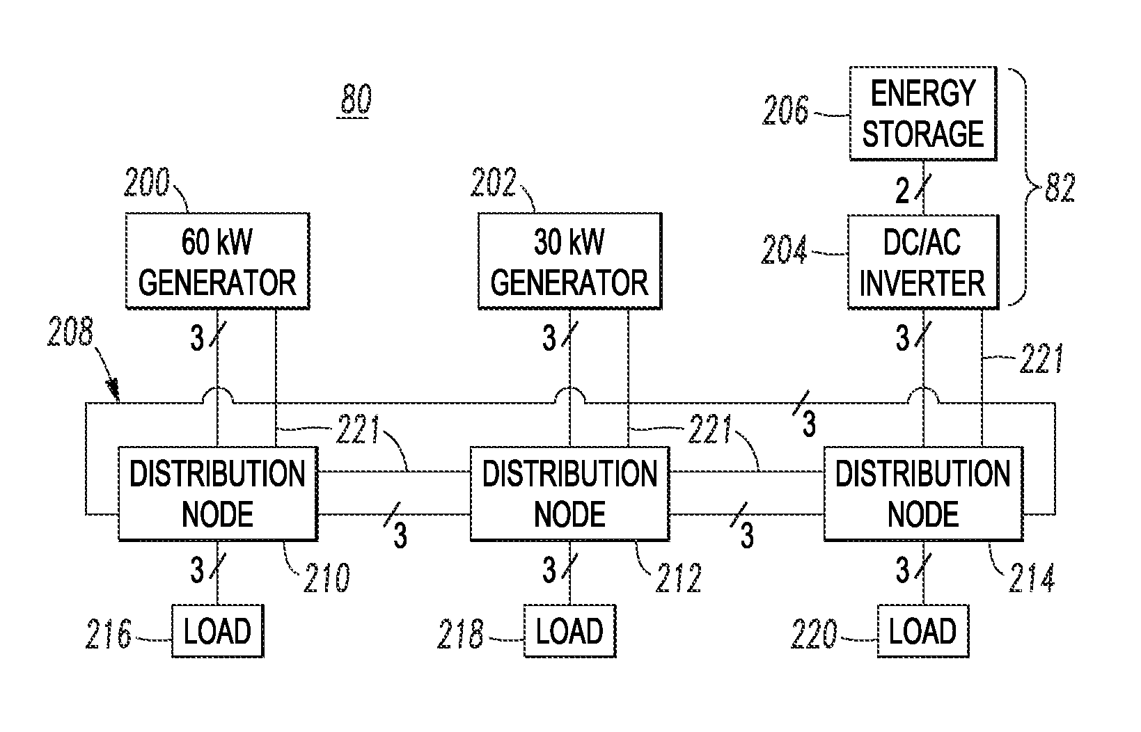
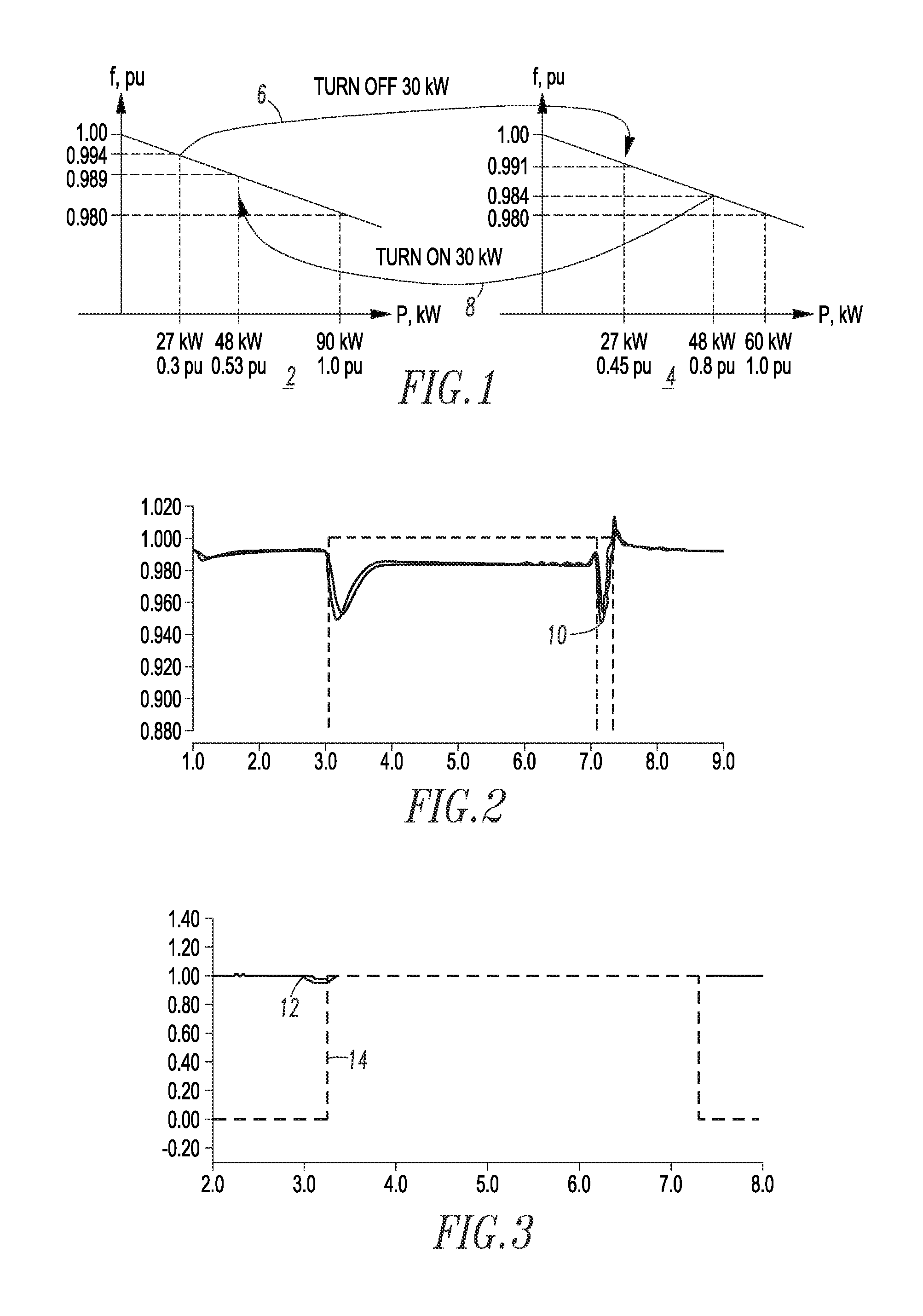
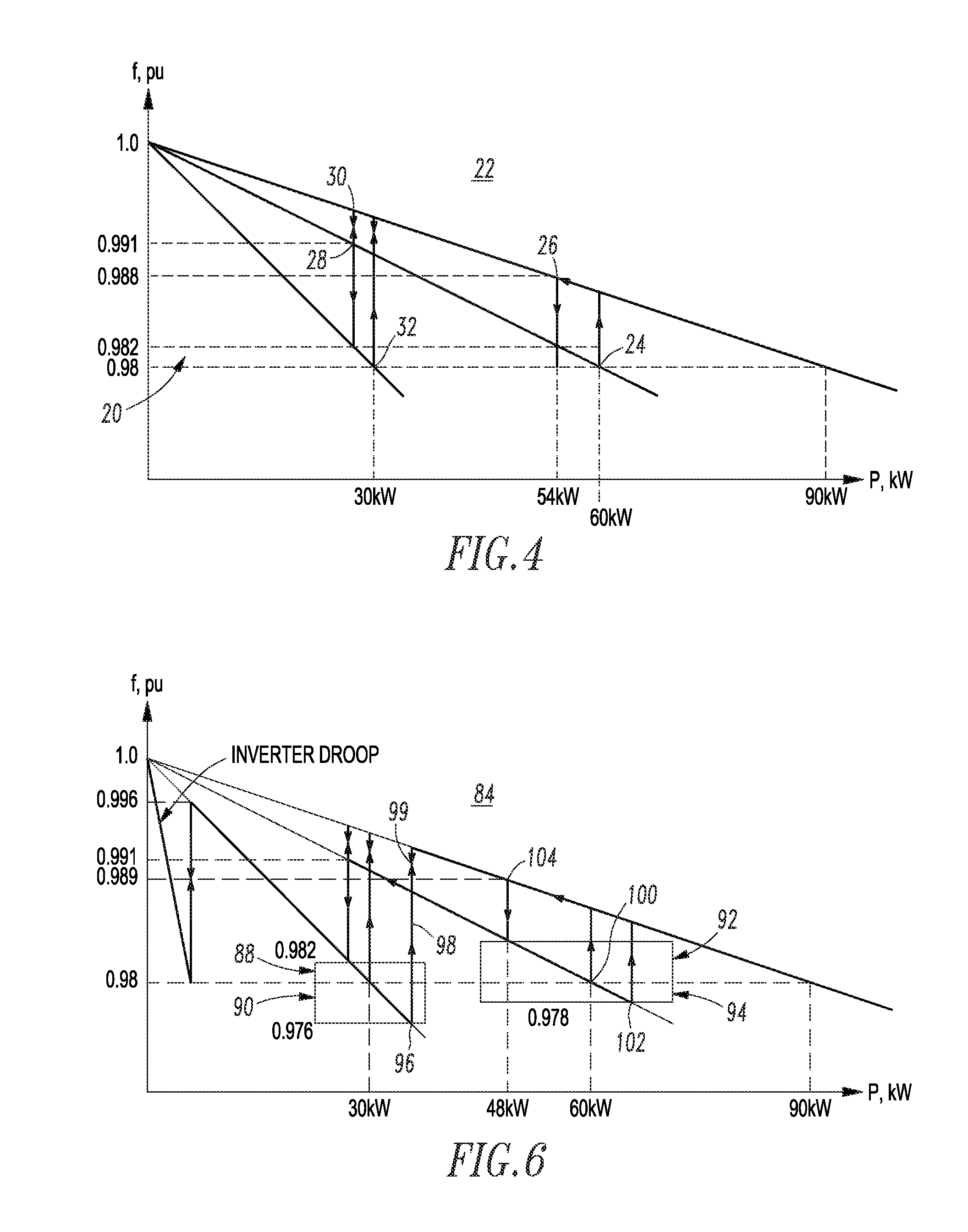
[0045]Diesel generation, for example, runs at maximum fuel efficiency when operated at rated power. Hence, in order to maximize overall system fuel efficiency, diesel DG needs to be operated at or near its nominal load rating as often as possible. There are two primary strategies available to accomplish this goal from a microgrid control architecture: (1) generator dispatching; and (2) peak shaving of generators. The efficiency bands disclosed herein are intended to provide the highest operational efficiency for diesel DG sourcing power to the microgrid, while ensuring reserve capacity in the diesel DG or a battery interface module (BIM) when connected to prevent a contingency from overloading the running diesel DG from an unanticipated surge in demand.

example 2

[0046]A BIM is, for example, a three-phase, four-wire grid tie inverter rated for the continuous capacity of the corresponding energy storage system (e.g., without limitation, rated at 6 kWH), and a transient capacity of the diesel DG that it is paired with. The BIM interfaces an energy storage system with the microgrid by providing equivalent voltage, frequency and phase of the diesel DG sourced power. The BIM functions as a complementary source for peak shaving for the diesel DG by adding transient demand power when the diesel DG is running near 100% capacity. This allows continued operation at the highest diesel DG efficiency for a relatively short time without transferring the demand to a higher rated diesel DG running at less than capacity and incurring additional losses in efficiency. At extreme low demand, the BIM is available to assume sourcing for the entire microgrid, thereby allowing the diesel DG to cycle off. This allows for the stored energy accumulated during power cy...

example 3

[0047]Generator dispatching consists of having just the right amount of diesel DG operating on the system to ensure that the generation capacity and load demands are balanced at any given time. This strategy implies that diesel DG of different ratings are on stand-by to be turned on or off as needed based on the present load demand. To have the effective control for stable and efficient paralleling of widely distributed diesel DG, voltage and frequency droop control is employed as modified by the use of efficiency bands as will be described.


PUM


Abstract

A microgrid power generation system includes a plurality of generators having a plurality of different rated capacities and a plurality of distribution nodes, at least some of the distribution nodes being powered by the generators. A grid is formed by the distribution nodes, the grid includes a system frequency. A plurality of loads are powered by the grid through the distribution nodes, the loads have a power demand. A processor includes a plurality of efficiency bands, each of the efficiency bands being for a corresponding one of the generators and including a plurality of generator switching points based upon droop of the system frequency and the power demand of the loads. The processor is structured to operate the generators and the loads under transient conditions based upon the efficiency bands.

Description

CROSS-REFERENCE TO RELATED APPLICATION[0001]This application claims priority from and claims the benefit of U.S. Provisional Patent Application Ser. No. 61 / 710,905, filed Oct. 8, 2012, which is incorporated by reference herein.BACKGROUND[0002]1. Field[0003]The disclosed concept pertains generally to power generation systems and, more particularly, to microgrids, such as, for example, distributed generation power systems. The disclosed concept further pertains to generator dispatching control methods for microgrids. The disclosed concept also pertains to load shedding control methods and systems.[0004]2. Background Information[0005]Fuel consumption and power reliability are two major concerns for power generation applications. In order to have a robust solution, the trend in power generation systems is developing toward distributed generation (DG) which includes conventional grid connect, conventional fossil fuel generation and renewable energy resources.[0006]A typical approach for ...

Claims


Application Information

Patent Timeline
Patent Type & Authority Applications(United States)
IPC IPC(8): H02J3/04
CPCH02J3/04H02J3/32H02J3/46Y02P80/14G05F1/66H02J3/381H02J2310/10H02J2300/10H02J2300/20H02J3/38Y02E70/30
Inventor PIYABONGKARN, DAMRONGRITBUCK, EDWARD F.DIMINO, STEVEN A.
Owner EATON INTELLIGENT POWER LTD
Why Eureka
Try Eureka